Use elements to change simulation
Elements can be added to a simulation to alter the flow of water. Channels permit water to flow lower than the flat elevation surface as though passing through a cut in the real world surface. Water sources introduce additional water to the simulation. Barriers alter the flow of water by blocking its current path and forcing it to follow another. Water sinks remove water within an area, with the option to transfer it elsewhere in the area of interest of the simulation. A simulation can include any combination of these elements.
Add a channel
Use channels to permit water to flow through ridges in the elevation surface. For example, create a channel to mimic water exiting through a gap in a damaged levee or dam.
On the Simulation tab, in the Insert group, click the Channel button
 .
.The Channel overlay appears.
Optionally, change the default name of the new channel.
Configure the diameter for the channel.
Click twice in the view to draw the channel.
Note:
Only two point lines are supported.
Optionally, preselect a single linear feature, for example a potential breach line, and click the Import geometry from the selected line feature button
 .
.The selected geometry is loaded into the new element and clipped to the extent of the simulation layer.
Click the green check mark
 to apply the channel to the simulation layer.
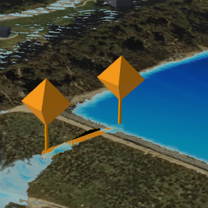
An orange line with orange pushpins at each end appears and the channel is added to the simulation in the Contents pane under the Drainage heading.
To add additional channels to the simulation, repeat steps 2 through 6 as needed. Alternatively, enable the Auto Apply button to create a channel using the same settings with each drawing.
When you are finished adding channels, close the overlay using the Close button
 or change the active tool.
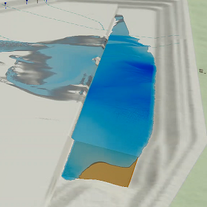
Add a water area
Use a water area to introduce additional water into a simulation. For example, add one water area to create a scenario in which a large body of water continuously flows into an area, such as a rise in sea level.
On the Simulation tab, in the Insert group, click the Water Area button
 .
.The Create Water Area overlay appears.
Optionally, change the default name of the new water area.
Configure the duration and rate for the water area.
Optionally, click the orange arrow
 to load a set of water rates or the green arrow
  to save a set of water rates.
Optionally, chose the unit for the intake rate value.
ft—feet
m—meter
Optionally, provide the Rate transition (minutes) value.
This defines the amount of time used to transition between flow rates.
Click in the view to draw the water area.
Optionally, preselect a single polygon feature—such as an ocean or river area—and click the Import geometry from the selected polygon feature button
.The selected geometry is loaded into the new element and clipped to the extent of the simulation layer.
Click the green check mark
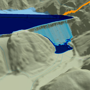
to apply the water area to the simulation layer.A dark blue polygon appears and the water area is added to the simulation in the Contents pane under the Water Sources heading.
To add additional water areas to the simulation, repeat steps 2 through 9 as needed. Alternatively, enable the Auto Apply button to create a water area using the same settings with each drawing.
When you are finished adding water areas, close the overlay using the Close button
or change the active tool.Tip:
Check Contain water within the area of interest in the Configure Simulation pane to fill an area with water (instead of letting it drain) to mimic localized flooding.
Add a barrier
Use barriers to alter the path of water as it flows along the surface. For example, create a barrier to replicate the use of sandbags to prevent localized flooding.
Note:
Water does not flow under a barrier or any vector feature in the view. It acts as a dam. When the terrain elevation is captured at the start of the simulation, a top-down view is considered, causing all barriers to stretch to the ground so that there is no gap underneath.
On the Simulation tab, in the Insert group, click the Barrier button
 .
.The Barrier overlay appears.
Optionally, change the default name of the new barrier.
Provide the height and width.
Note:
Barriers must be wider than the cell size.
Optionally check the Densify option.
Additional vertices will be added to the resultant barrier so that it more closely follows the terrain.
Click in the view to draw the barrier line.
Optionally, preselect a single linear feature—such as a line of K-rails—and click the Import geometry from the selected line feature button
.The selected geometry is loaded into the new element and clipped to the extent of the simulation layer.
Double-click or press F2 to finish the drawing.
Click the green check mark
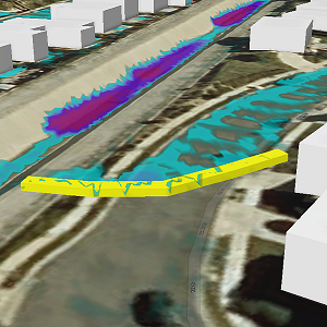
to create the barrier.A yellow barrier is created along the drawn path and the barrier is added to the simulation in the Contents pane under the Barriers heading.
To add additional barriers to the simulation, repeat steps 2 through 8 as needed. Alternatively, enable the Auto Apply button to create a barrier using the same settings when you finish each drawing.
When you are finished adding barriers, close the overlay using the Close button
or change the active tool.
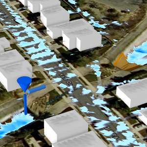
Add a water source
Use water sources to introduce additional water into a simulation. For example, add one water source to create a scenario in which a single fire hydrant has been sheared or add multiple to imitate incoming water flow for a localized flooding event. Optionally, use a water source to transfer water from a water sink to create a scenario in which water appears to be pumped from one location to another.
Tip:
Water source points inject water into the simulation within a 5-meter area. When you try to inject very large volumes of water—such as 200 cubic meters per second—and place it on an area too small to hold it, mounding will occur. When such large volumes of water are needed, choose the Water Area element instead.
Use a water source to add water
To add water to a simulation using a water source, complete the following steps:
On the Simulation tab, in the Insert group, click the Water Source button
 .
.The Water Source overlay appears.
Optionally, change the default name of the new water area.
Verify that the Mode parameter is set to Add. This default mode adds water into the simulation similar to how a sheared hydrant or burst pipe might.
Configure the duration and water flow rate for the source.
Optionally, click the orange arrow
to load a set of water rates or green arrow to save a set of water rates.Click in the view to place the water source.
Click the green check mark
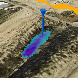
to apply the water source to the simulation layer.A blue inverted cone appears at the clicked location and the water source is added to the simulation in the Contents pane under the Water Sources heading. The size of the cone is based on the initial flow rate.
To add more water sources to the simulation, repeat steps 2 through 7 as needed. Alternatively, enable the Auto Apply button to create a water source using the same settings with a single click.
When you are finished adding water sources, close the overlay using the Close button
or change the active tool.
Use a new water source to transfer water from a sink area
To use a new water source to move water from a sink area, complete the following steps:
On the Simulation tab, in the Insert group, click the Water Source button
.The Water Source overlay appears.
Optionally, change the default name of the new water area.
Change the Mode parameter to Transfer. This mode takes water from a water sink and injects it at the water source.
Note:
The simulation must contain at least one sink area for this mode to be available.
Select a sink area as the Intake.
Click Connect.
The sink area name appears in the list. The water travel direction, uphill
 or downhill
  , is indicated in the Travel (secs) column which shows the time required to travel between the two elements. The time required value can be manually changed, or you can click the travel direction button to recalculate the value after editing the water source location. By default, uphill travel time is calculated using one meter per second and downhill travel time is calculated using Manning's equation which considers the slope, distance, and approximate size of the pipe between the sink area and the connected water source.
One water source can be connected to multiple water sinks. Repeat steps 4 and 5 until all connections are made.
Click in the scene to place the water source.
Click the green check mark
to apply the water source to the simulation layer.A blue inverted cone appears at the clicked location and the water source is added to the simulation in the Contents pane under the Water Sources heading. An additional cylinder shape is added to the symbol pointing towards each connected sink area.
To add more water sources to the simulation, repeat steps 2 through 8 as needed. Alternatively, enable the Auto Apply button to create a water source using the same settings with a single click.
When you are finished adding water sources, close the overlay using the Close button
or change the active tool.
Add a sink area
Use a water sink area to remove water from within a simulation or move water to another area. For example, add a water sink area to represent an entry point into a stormwater drain or a pumping station that moves water outside the area of interest. Alternatively, transfer water from a sink area to a water source point to represent the movement of water under a bridge.
Remove water using a sink area
A sink area can be used to remove water from within a simulation similar to an entry point into a stormwater drain.
On the Simulation tab, in the Insert group, click the Sink Area button
 .
.The Create Sink Area overlay appears.
Optionally, change the default name of the new water area.
Verify that the Mode parameter is set to Remove. This default mode removes water from the simulation similar to how a pumping station might.
Configure the duration and water flow rate.
Set the flow rate to indicate the volume of water being removed over the sink area. The maximum intake rate for a storm drain can be calculated by multiplying the surface area of the inlet, such as 2 square meters, by the maximum speed of the water in the drain, which is usually 3 m/sec or less.
Optionally, click the orange arrow
to load a set of water rates or the green arrow to save a set of water rates.Optionally, chose the unit for the intake rate value.
ft—feet
m—meter
Optionally, provide the Rate transition (minutes) value.
This defines the amount of time it takes to transition between flow rates.
Optionally, provide the Maximum intake (m³) value in numerals, with no commas.
This defines the total intake volume for the sink area. A value of 0 means infinite intake. The maximum allowable intake volume is 200,000 m³, which is the equivalent of approximately 53 million gallons or roughly 106 Olympic-sized swimming pools.
Click in the scene to draw the water sink area.
Optionally, preselect a single polygon feature, for example the intake area for a culvert, and click the Import geometry from the selected polygon feature button
.The selected geometry is loaded into the new element and clipped to the extent of the simulation layer.
Click the green check mark
to apply the sink area to the simulation layer.The water source is added to the simulation in the Contents pane under the Drainage heading.
To add more sink areas to the simulation, repeat steps 2 through 11 as needed. Alternatively, enable the Auto Apply button to create a sink area using the same settings. Double-click to complete each drawing, auto-apply the settings, and add the additional sink areas to the simulation.
When you are finished adding sink areas, close the overlay using the Close button
or change the active tool.
Transfer water from a sink area to a water source
Transfer water from a sink area to a water source within a simulation. For example, add a water sink area to represent water entering a culvert or bridge underpass and connect it to a water source so that the water emerges from the other side.
On the Simulation tab, in the Insert group, click the Sink Area button
.The Create Sink Area overlay appears.
Optionally, change the default name of the new water area.
Change the Mode parameter to Transfer. This mode moves water from the water sink and injects it at the connected water source point similar to how a stormwater drainage system might.
Note:
The simulation must contain at least one water source for this mode to be available.
Configure the duration and water flow rate.
Set the flow rate to indicate the volume of water being removed over the sink area. The maximum intake rate for a storm drain can be calculated by multiplying the surface area of the inlet, such as 2 square meters, by the maximum speed of the water in the drain, which is usually 3 m/sec or less.
Optionally, click the orange arrow
to load a set of water rates or the green arrow to save a set of water rates.Optionally, chose the unit for the intake rate value.
ft—feet
m—meter
Optionally, provide the Rate transition (minutes) value.
This defines the amount of time it takes to transition between flow rates.
Note:
As the sink area is transferring water to an outlet location, the water has a place to exit the sink area. Since it cannot reach maximum capacity a Maximum intake (m³) value of 0 is seen which means infinite intake. This value cannot be changed.
Choose the Output location from the list of existing water source point names.
Click in the view to draw the water sink area.
Optionally, preselect a single polygon feature—such as a storm drain—and click the Import geometry from the selected polygon feature button
.The selected geometry is loaded into the new element and clipped to the extent of the simulation layer.
Click the green check mark
to apply the sink area to the simulation layer.The water source is added to the simulation in the Contents pane under the Drainage heading.
To add more sink areas to the simulation, repeat steps 2 through 11 as needed. Alternatively, enable the Auto Apply button to create a sink area using the same settings. Double-click to complete each drawing, auto-apply the settings, and add the additional sink areas to the simulation.
When you are finished adding sink areas, close the overlay using the Close button
or change the active tool.
Modify an element
The properties of an element in a simulation can be changed after it is created.
To update the location or properties of an element, right-click the element in the Contents pane and click Modify
 .
.The corresponding overlay opens.
Adjust the values or location of the element.
Click the green check mark
to apply your changes.The simulation must be run again to capture these changes.
Click the Run button
 in the Build group of the Simulation tab to rebuild the simulation.
Remove an element
You can remove an element from the view and the simulation.
To remove an element, right-click it in the Contents pane and click Remove
 .
.The simulation must be run again to capture this change.
Click the Run button
in the Build group of the Simulation tab to rebuild the simulation.