Add the Meter Reference Guide
![]() Available with an ArcGIS Topographic Mapping license.
Available with an ArcGIS Topographic Mapping license.
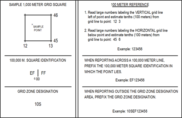
The Meter Reference Guide element provides a set of instructions and examples that allow you to compose standard grid references. It also contains diagrams for identifying the grid zone and grid square designations on the map sheet. This element's properties update based on the associated data frame's coordinate system.
Note:
If a grid mask feature class (MSK_<grid_name>) is in the layout view, the Meter Reference Guide element prevents the display of 100,000 M. Square Identification coordinates beyond the area the mask surrounds.
If the map extent appears coincident with an MGRS 100,000 meter-square boundary, the Meter Reference Guide element displays the 100,000 M. Square Identification coordinates on both sides of the boundary.
Insert a Meter Reference Guide
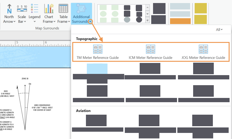
There are three types of Meter Reference Guide elements designed to accommodate the Topographic Map (TM), Image City Map (ICM), and Joint Operations Graphic (JOG) map specifications. To add a Meter Reference Guide element to a map layout, complete the following steps:
Ensure that a layout with a map frame is open and is the active view in your project.
Click the Insert tab.
In the Map Surrounds group, click the Additional Surrounds drop-down arrow and choose a meter reference guide from the Topographic section.
Click an insertion point in the active layout to place the new Meter Reference Guide element.
The Meter Reference Guide is added to the layout and remains selected.
Modify the Meter Reference Guide
You can modify the properties and appearance of a Meter Reference Guide using the options on the Meter Reference Guide contextual tab, as well as the Element pane.
Open the layout that contains the Meter Reference Guide that you want to modify and ensure that it is the active view in your project.
Double-click the element in the Contents pane to open the Element pane and update more element properties as necessary.
Tip:
You can also right-click the element on the layout or in the Contents pane and click Properties
 to open the Element pane.
In the Element pane, click the Options tab
.Provide a name for the element in the Name text box.
This name appears in the Contents pane and must be unique.
Specify whether the element is visible by checking or unchecking the Visible check box.
The default is visible.
Specify whether the element is locked so that changes cannot be made by checking or unchecking the Locked check box.
The default is unlocked.
Specify whether the element appears at a fixed height and width according to the specifications of the map product by checking or unchecking the Draw To Specification check box.
If the Draw To Specification check box is checked, the element cannot be resized.
Click the Map frame drop-down arrow to change the map frame associated with the element.
Click the Type drop-down arrow to specify the type of cartographic product associated with the element.
The element's appearance changes depending on the cartographic product specified.
Click the Color drop-down arrow to change the element's color.
Expand Accessibility and provide alt text for the element in the Alt Text text box.
Tip:
Assistive technologies can read this text when a PDF is exported.
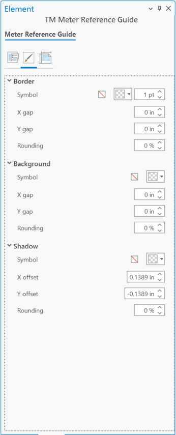
In the Element pane, click the Display tab
 to set the element's appearance:
Configure the element's border in the Border section.
Configure the element's background in the Background section.
Configure the element's shadow in the Shadow section.
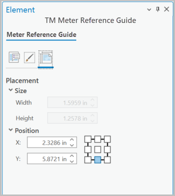
In the Element pane, click the Placement tab
 to set the element's placement options.
Specify the element's size.
Resizing is unavailable if the Draw To Specification check box on the Options tab
is checked.Specify the element's position.
These settings can also be set from the element's contextual tab in the Size & Position group.
The element is configured as specified. You can continue to modify it or the layout as necessary.