Simplify By Straight Lines And Circular Arcs (Editing Tools)
Summary
Simplifies polygon and line features by replacing consecutive line segments or edges with fewer line segments or edges. Lines segments and polygon edges are simplified based on a specified maximum allowable offset. Additionally, circular arcs can be created from consecutive line segments or polygon edges.
Illustration
Usage
Caution:
This tool modifies the input data. See Tools that modify or update the input data for more information and strategies to avoid undesired data changes.
This tool can be used to simplify the geometry of line and polygon features that have accumulated unwanted vertices or short segments from various data conversion and manipulation processes. Sequences of nonlinear segments or edges can be replaced by two-point straight lines, and a series of segments or edges representing arcs can be replaced by true curves. This tool will approximate and replace multiple segments or edges with straight lines and circular arcs that fit within a specified maximum allowable offset.
Input features can be polygons or lines. The output line or polygon edge will contain a subset of its original vertices. New vertices will not be introduced and no features will be deleted.
Existing parametric curves, such as Bézier curves, circular arcs, and elliptical arc segments will not be changed.
Note:
If the input features are stored in a shapefile, circular arcs in the output features will remain a densely populated series of small straight segments. Shapefiles do not support true curves. To derive true curves, export the shapefile to a feature class.
Use the Create circular arcs parameter to generate true curves in addition to straight lines. The five optional parameters, Maximum Arc Angle Step, Minimum Number Of Vertices, Minimum Radius, Maximum Radius, and Minimum Arc Angle, control how circular arcs will be fitted to segments or edges.
Maximum Arc Angle Step (decimal degrees) is the maximum arc angle that can be used to construct circular arcs. The arc angle is the central angle of the candidate curve (the curve that is being constructed). The maximum arc angle step defines the upper limit of how wide the central angle search field can be when locating vertices to construct circular curves. If more than one vertex is found within each maximum arc angle step, these vertices will be considered for fitting to a circular arc. Use a smaller arc angle to fit circular arcs to densely distributed segments and to prevent the over-fitting of circular arcs to large segments. Use a larger arc angle to fit circular arcs to sparsely distributed segments. The valid value range is from 2 through 95 decimal degrees. The default is 20 decimal degrees.
In the image below, a segment with a 90 degree central angle is considered for the fitting of a circular arc. If 89 degrees is specified as the maximum arc angle step, the segment is not considered and the output consists of a curve and a straight line (middle diagram). If 91 degrees is specified, the segment is used to construct the circular arc, and the output consist of a single curve (end diagram).
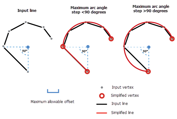
The Maximum Arc Angle Step parameter is used to locate vertices to construct circular arcs. -
Note:
The Maximum Arc Angle Step parameter is not available if the Fit to segments option is specified for the Fitting Type parameter.
Check the Preserve endpoints for closed line parameter to preserve the endpoints of a line that has coincident end points (loop). If the Preserve endpoints for closed line parameter is unchecked, the endpoints can be moved or deleted.
To maintain existing topological integrity, ensure that all layers that should be topologically coincident are included as input when running the tool.
Parameters
| Label | Explanation | Data type |
|---|---|---|
|
Input Features |
The features that will be simplified. Features can be lines or polygons. If using multiple inputs, the features must have the same spatial reference. |
Feature Layer |
|
Maximum Allowable Offset |
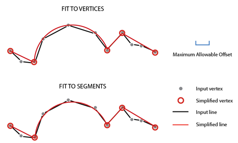
The maximum distance the output feature edges can deviate from the input feature shapes. When the Fit to vertices option is specified for the Fitting Type parameter, the distance is measured between the input position of the vertices and the updated output position of the feature edges. When the Fit to segments option is specified, the distance is measured between the position of the input feature edges and the updated output feature edges. The value used is typically in the range of 0.01 meters (0.03 feet) to 2 meters (6 feet). When using the Fit to segments option, use a larger tolerance. When using the Fit to vertices option, use a smaller tolerance. Use the Fit to vertices option when the input features have more precisely defined shapes. |
Linear Unit |
|
Fitting Type (Optional) |
Specifies how the output feature edges and circular arcs will be fitted to the input feature shapes. If the Fit to segments option is specified, the Maximum Arc Angle Step (decimal degrees) and Minimum Number Of Vertices parameters are not available.
|
String |
|
Create circular arcs (Optional) |
Specifies whether circular arcs will be created.
|
Boolean |
|
Maximum Arc Angle Step (decimal degrees) (Optional) |
The maximum arc angle step (decimal degrees) that will be used to construct circular arcs. The arc angle defines how wide the visual field can be, for each step, when locating vertices to construct circular curves. The arc angle is the central angle of the candidate curve (the curve that is being constructed). If vertices are found within each maximum arc angle step, a circular arc is constructed. For example, if vertices and edges are sparse, use a large arc angle step. The valid value range is from 2 through 95 decimal degrees. The default is 20 decimal degrees. This parameter is not available if the Fit to segments option is specified for the Fitting Type parameter. |
Double |
|
Minimum Number Of Vertices (Optional) |
The minimum number of vertices required for a circular arc to be created. The value must be greater than 3. The default is 4. This parameter is not available if the Fit to segments option is specified for the Fitting Type parameter. |
Long |
|
Minimum Radius (Optional) |
The smallest allowable radius for output circular arcs. The value must be greater than 0 and smaller than the Maximum Radius parameter value. If no value is specified, the radius of the output circular arcs will not be considered (default). |
Linear Unit |
|
Maximum Radius (Optional) |
The largest allowable radius for output circular arcs. The value must be greater than the Minimum Radius parameter value. If no value is specified, the radius of the output circular arcs will not be considered (default). |
Linear Unit |
|
Minimum Arc Angle (decimal degrees) (Optional) |
The minimum arc angle (decimal degrees) that will be used to construct circular arcs. The minimum arc angle is the smallest allowable central angle in the output circular arcs. If the central angle of any output circular arc is less than this value, it will not be created. The valid value range is from 2 through 360 decimal degrees. The default is 2 decimal degrees. |
Double |
|
Preserve endpoints for closed line (Optional) |
Specifies whether the endpoints of a closed line will be preserved. A closed line is a line that has coincident end points (loop).
|
Boolean |
|
Anchor Points (Optional) |
The path and name of the feature class that contains anchor points. Anchor points overlay vertices on the input features and indicate that they should not be moved or deleted in the simplify process. |
Feature Layer |
Derived output
| Label | Explanation | Data type |
|---|---|---|
|
Output Features |
The updated features. |
Feature Layer |
|
Output Layer Names |
The updated layer names. |
Feature Layer |
Environments
Licensing information
- Basic: No
- Standard: Yes
- Advanced: Yes