Tutorial: Process Drone Imagery in Reality Web App
Note:
ArcGIS Reality Web App is a beta feature at ArcGIS Enterprise 12.2. While in beta, this capability may not be feature complete and, as such, may have known performance or quality issues and will not be supported by Esri Technical Support.
Feedback on this feature can be provided through the Esri Early Adopter Community.
This tutorial walks through a complete workflow for processing drone images with ArcGIS Reality Web App. First, you will create a project and add a GCP set. Next, you will create a mission for the drone images and perform initial processing. Then you will tag GCPs in some of the images and reprocess the missions with the GCPs applied to generate 2D and 3D products, and finally review the processing report.
A collection of 195 drone images covering a section of the Esri campus, California, is provided for this tutorial. Each image has embedded EXIF metadata which is used along with the supplied GCP’s to support the block adjustment process. Download the tutorial dataset and unzip to a preferred folder.
Important:
To use Reality Web App, you need to be a member of an ArcGIS Enterprise organization with Reality Server capability and be assigned Reality Analyst role.
Create a project
The first step in the workflow is to create a project. A project is a top-level workspace for a site, for organizing the GCP sets, members, settings and missions for that location. Every collection of images must be associated to a project. Complete the following steps to create a project for this work:
Sign into ArcGIS Enterprise using an account with Reality Analyst role.
From the App Launcher, click Reality Web App button to start the app. The opened page lists all the projects for your organization that you have access to.
Alternatively, members can sign in directly at
https://<domain name>.com/<web adaptor name>/apps/reality.Click
+ New Projectto launch new project wizard.On the Project details tab, provide the
Project title, and optionally addTagsand aSummary.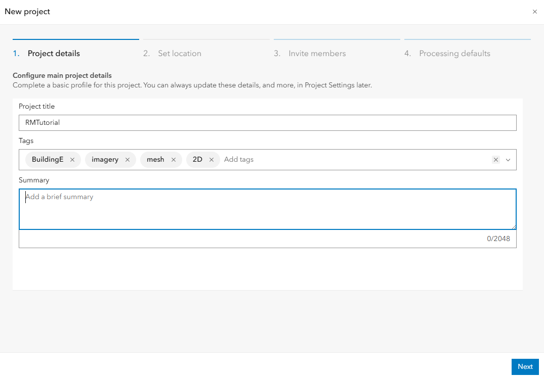
Click
Next. A tab for setting the project location appears. The demo images were collected over a section of the Esri campus, California.On the
Set locationtab, EnterEsriin the search bar and select the first option (Esri, 380 New York St, Redlands, CA, 92373, USA) to drop a pin on the project site.Note:
The horizontal coordinate system and vertical coordinate system fields populate automatically from the pin location (typically the local WGS 1984 UTM zone and EGM height) but can be changed manually if the project requires a different reference system.
Click
Next. A tab for inviting organization members to the project appears.On the
Invite memberstab, search for organization members and clickAddnext to anyone who needs access to the project. This step is optional and can be done later from the project's Members tab.Click
Next.On the
Processing defaultstab, toggle on all products and leave the product quality as High. This sets the type and quality of Products to generate by default for every mission in this project.Click
Create. The project will be created and opened.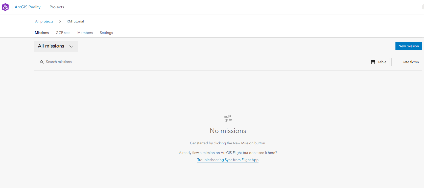
In this step, you have just set up a project for the drone images you want to process. You can explore the project content by clicking the Missions, GCP sets, Members or Settings tab. The project currently have no gcp set or mission. In the next two steps, we will add a GCP set and then create a mission.
Add a GCP set to the project
GCPs are points with known x,y,z ground coordinates, which are often obtained from ground survey to improve the absolute accuracy of adjusted imagery. GCPs are saved at the project level so the same set can be used to georeference multiple missions. Complete the following steps to add GCP acquired for the project:
On the project page, click the
GCP setstab and click+ Add from CSV. The file browser opens.Browse to the the downloaded folder and select the
Tut_Ground_Control_UTM11N_EGM96.csvfile. ClickOpen.In the
Add Ground Control Points from CSV Filedialog, typeGCP_1as the GCP set name and ensure that the Delimiter is set as Comma.The GCP CRS is assumed to be in same CRS as the project but the horizontal CRS of the GCP is NAD 1983 UTM Zone 11N not WGS 84 UTM Zone 11, so we will modify this:
Click the horizontal coordinate system field to open the coordinate system tree.
Expand Projected Coordinate Systems > North America > Zone Series > UTM (NAD 1983) and chose EPSG:26911 - NAD 1983 UTM Zone 11N.
Map the GCP fields accordingly as shown below
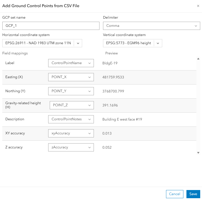
Click
Save.The new GCP set appears in the GCP Sets table with its upload date, coordinate system, and point count. Now, we are set to create a mission.
Create a mission
A mission holds the imagery and processed products for a single data-capture session. Complete the following steps to create a mission for our acquisition and start processing:
On the project's page, click the
Missionstab and click+ New mission. TheNew missiondialogue appears.On the
mission detailstab, typemission 1and chooseArea Surveyas the mission type.Turn on
Auto-process the mission after it is createdso block adjustment begins as soon as the images finish uploading. This reveals the same Products and Product quality settings as the project defaults, which can be overridden for this mission only. We want to do initial block adjustment at this stage to facilitate GCP tagging so we don't need to generate any product for now.Turn off all product and click
Next.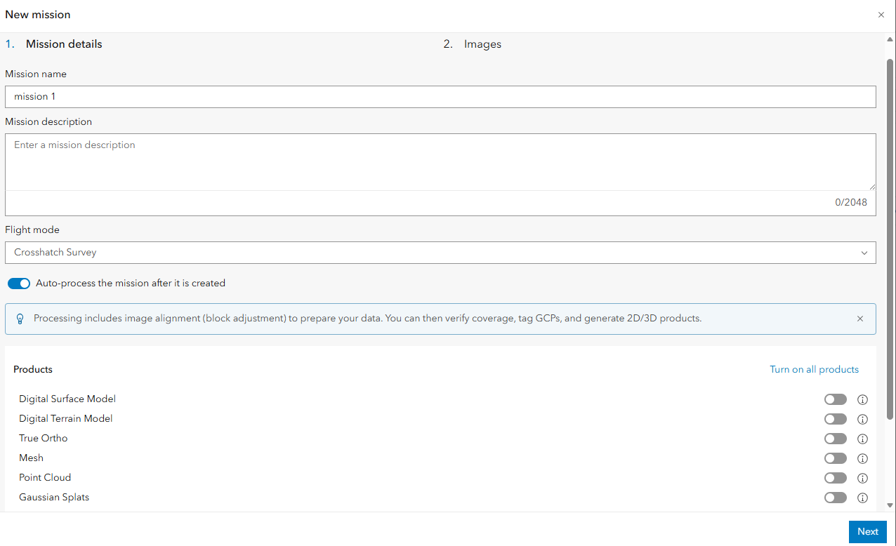
On the
Imagestab, drag the drone images into the upload area or click Browse files to select them.Review the image table and the Minimum requirement check panel on the right, which confirms that Location information (from image EXIF data) and the Camera model were both detected. Confirm the Output coordinate system.
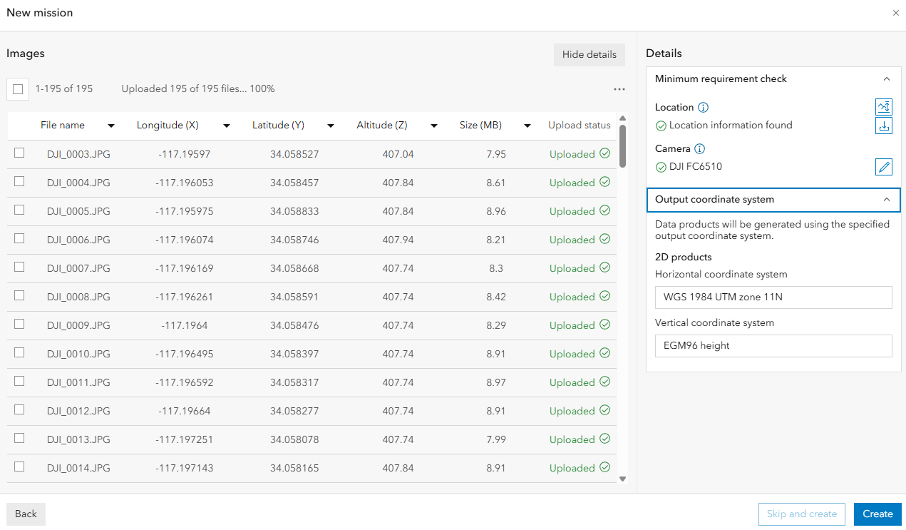
Click
Create.The mission page opens while with image collection and initial block adjustment process going on. After the process is completed, a process report is generated and can be viewed by clicking the
view processing report.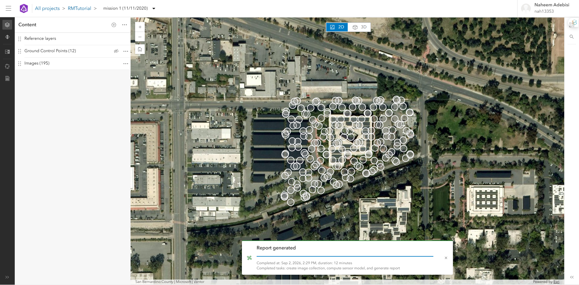
Review and tag ground control points
The initial adjustment relies only on the images' GPS metadata, so its absolute accuracy is limited. Tagging GCPs against the actual imagery is necessary to improve the result accuracy. Complete the following steps to tag the GCPs:
On the mission's toolbar, click
Review Ground Control Points. The Review Ground Control Point dialog box opens.In the
Choose GCP Setdropdown, confirm the correct GCP set is selected.Hover on a GCP in the GCP list table (or on the Map) to see candidate images that may contain the GCP marker highlighted in orange.
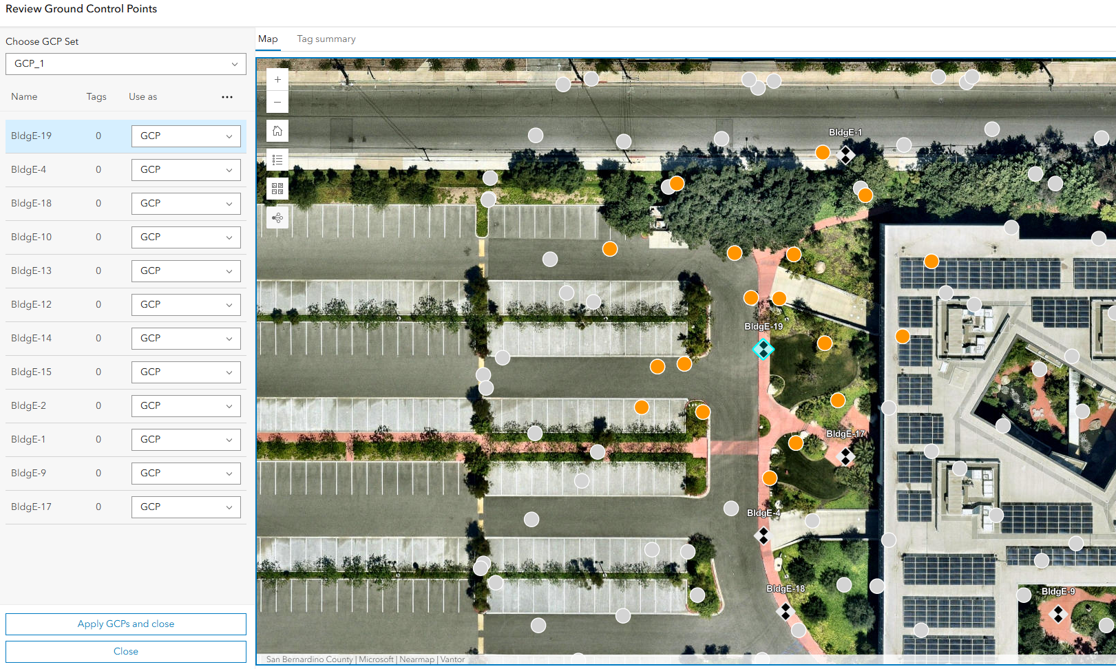
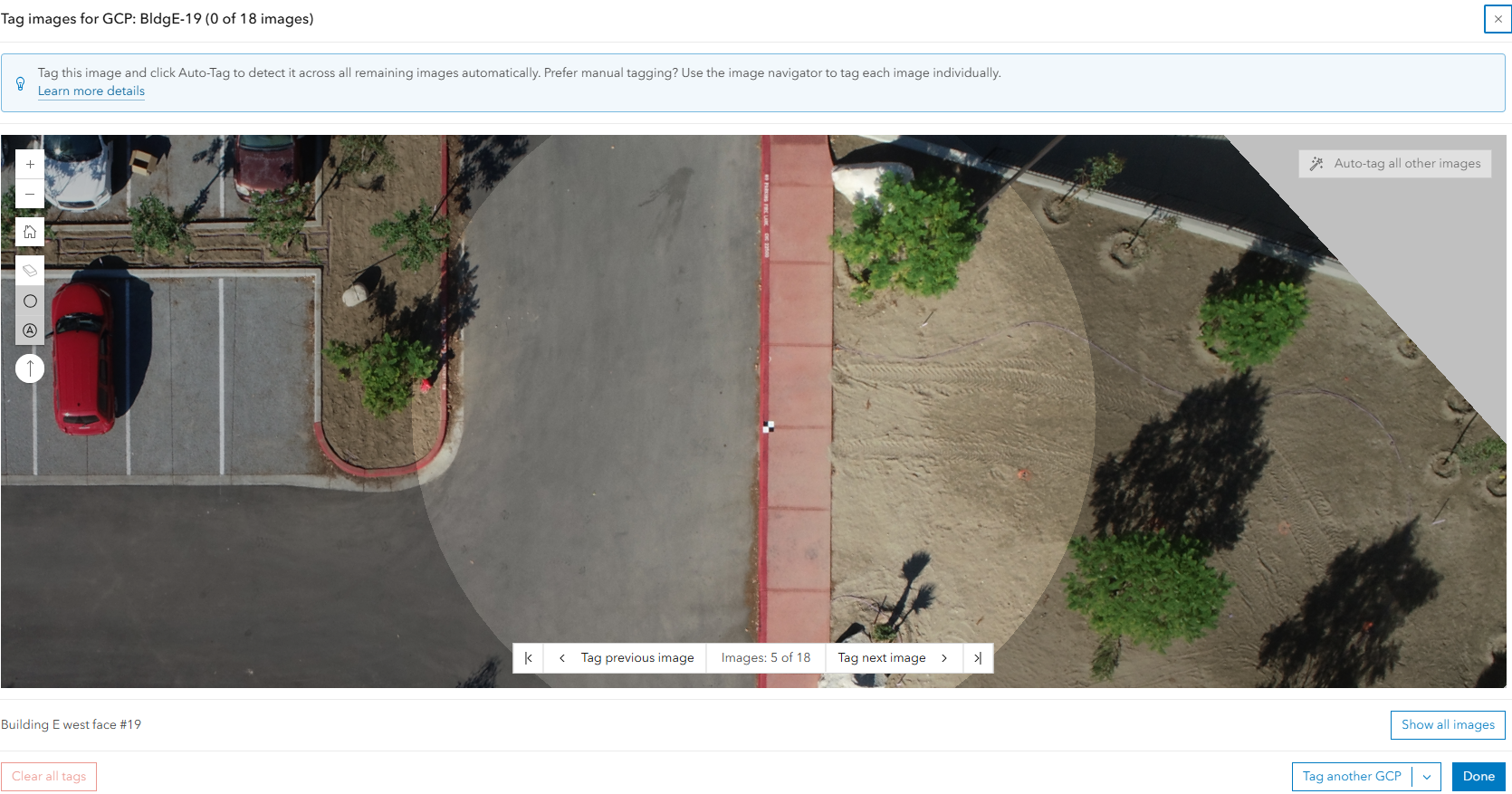
Click one of the candidate images to open it for GCP tagging, with potential GCP location highlighted in circle.
Note:
Clicking the GCP instead of the candidate image opens all candidate images in Grid view for tagging.
Find and tag the GCP by clicking the precise marker location in the image. A blue cross will appear for tagged GCP. After tagging the GCP on one image, the
Auto Tagoption at the top right also becomes active and can be used to find the marker in the other images.Click
Auto Tagto automatically find GCP in other images or continue manual tagging by clicking<>in the bottom to move to another candidate image and repeating step 5. At least three tags are required for each GCP.Note:
Tip: The Auto Tag button attempts to locate the same target automatically across the remaining candidate images once it has been tagged in one image, and automatically switches to Grid View mode. In this mode, candidate images for a GCP are listed in a grid, facilitating tagging and review of multiple images at once.

Repeat the tagging process for every other GCPs:
- Click
Tag another GCPdropdown on the bottom right to select another GCP to tag from GCP list or clickDoneto go to back to theReview Ground Control Pointsdialogue and repeat steps 3-6.
- Click
After tagging all GCPs, close the image tagging window to go back to the
Review Ground Control Pointswindow. All tagged GCPs are highlighted in green on the map the GCP table's Tags column also shows the tag count.From the dropdown of the GCP list table, change BldgE-1 to a check point. The GCP color changes to purple.

Click
Apply GCP and closeat the bottom of the panel.
Reprocess the mission
Reprocessing after tagging GCPs re-runs the full block adjustment and generates or regenerates the mission's products using the newly tied-down control points. Complete the following steps if the mission needs to be processed again with different settings:
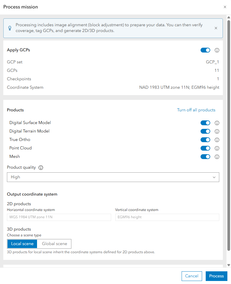
On the mission's toolbar, click Process mission.
Confirm Apply GCPs is turned on, and review the GCP set, number of GCPs, Checkpoints, and Coordinate System summary.
Review or adjust the Products, Product quality, and Output coordinate system settings for this processing run.
Click Process.
View the processing report
Every completed adjustment produces a report that summarizes accuracy and flags anything that needs attention. Complete the following steps to review it:
On the mission's toolbar, click View Processing Report.
Review the Adjustment Summary table for the key statistics of the run.
Summary
In this tutorial, you created a Reality project, imported a ground control point set, created a mission for drone images and performed initial processing, tagged GCPs against the source imagery to tie the block to surveyed coordinates, reprocessed the mission with those GCPs applied, and reviewed the resulting adjustment report.