Oriented imagery table
An oriented imagery table defines metadata for a collection of images. It is used as an input to the Add Images To Oriented Imagery Dataset geoprocessing tool.
The oriented imagery table can be used for adding images in the following instances:
The image metadata is stored separately from the image files.
The image metadata needs preprocessing before oriented imagery dataset inclusion.
You want to use the image orientations defined by the
Matrix, orOmega,Phi, andKappafields.
Note:
If any of the optional fields in the oriented imagery table has the same value for all images and the field is an oriented imagery dataset property, a value for the field can be defined in the oriented imagery dataset property and removed from the oriented imagery table. For example, if all images use the same elevation source, the field can be defined as an oriented imagery dataset property, assigned the common value, and removed from the oriented imagery table. All the images will use the same value for the elevation source.
Oriented imagery table fields
The fields supported in the oriented imagery table are listed below. When a field is defined in the oriented imagery table, it takes precedence over the definition in the oriented imagery dataset properties. Additional fields in the oriented imagery table can be included in the output oriented imagery dataset if the Include all fields from input table parameter is checked in the Add Images To Oriented Imagery Dataset tool.
Fields supported in the oriented imagery table
|
Field name |
Field type |
Data type |
Description |
|---|---|---|---|
|
|
Required |
Numeric |
The x-coordinate of the camera location in the ground coordinate system. The units are the same as the coordinate system units defined in the |
|
|
Required |
Numeric |
The y-coordinate of the camera location in the ground coordinate system. The units are the same as the coordinate system units defined in the |
|
|
Optional |
Numeric |
The z-coordinate of the camera location in the ground coordinate system. The z-coordinate units must be consistent with the x- and y-coordinate units and can be defined by the vertical coordinate system. The z-coordinate is typically expressed as orthometric heights (elevation above sea level). This is appropriate when the input digital elevation model (DEM ) is also using orthometric heights. |
|
|
Optional |
String |
The coordinate system of the camera location as a well-known ID (WKID) or a definition string (well-known text [WKT]). If a value for |
|
|
Required |
String |
The path to the image file. This can be a local path or a web-accessible URL. Images can be in JPEG, JPG, TIF, or MRF format. |
|
|
Optional |
String |
An alias name that identifies the image. |
|
|
Optional |
Date |
The date when the image was collected. The time of the image collection can also be included. |
|
|
Optional* |
Numeric |
The camera orientation of the first rotation around the z-axis of the camera. The unit is degrees. The direction of measurement for heading is in positive clockwise direction, where north is defined as zero degrees. When the image orientation is unknown, -999 is used. |
|
|
Optional* |
Numeric |
The camera orientation of the second rotation around the x-axis of the camera. The unit is degrees. The direction of measurement for pitch is in positive counterclockwise direction. The |
|
|
Optional* |
Numeric |
The camera orientation of the final rotation around the z-axis of the camera in the positive clockwise direction. The unit is degrees. Valid values range from -90 to 90. If the camera is pointed toward the horizon and the rows of the image are parallel with the horizon, the value of |
|
|
Optional |
Numeric |
The height of the camera above the ground. It is used to determine the visible extent of the image in which large values result in a greater view extent. The unit is meters. Values assigned must be greater than zero. If the |
|
|
Optional |
Numeric |
The camera’s field of view in a horizontal direction. The unit is degrees. The valid values range from 0 through 360. |
|
|
Optional |
Numeric |
The camera’s field of view in the vertical direction. The unit is degrees. The valid values range from 0 through 180. |
|
|
Optional |
Numeric |
The nearest usable distance of the imagery from the camera position. This value determines the near plane of the visible frustum in a 3D scene. The unit is meters. |
|
|
Optional |
Numeric |
The farthest usable distance of the imagery from the camera position. This value determines the far plane of the visible frustum. The intersection of the frustum far plane with the ground defines the footprint, which is used to determine whether an image is returned when you click the map. The unit is meters. Values must be greater than zero. |
|
|
Optional |
String |
A pair of values, These values represent the offset between the following:
Specifying The |
|
|
Optional |
String |
Detailed camera orientation parameters are stored as a pipe-separated string. This field provides support for more accurate image-to-ground and ground-to-image transformations. |
|
|
Optional |
String |
The imagery type is specified from the following:
|
|
|
Optional |
Numeric |
The orientation of the camera in degrees relative to the scene when the image was captured. The valid values range from -360 through 360. The value is used to rotate the view of the image in the oriented imagery viewer to ensure the top of the image is up. |
|
|
Optional |
String |
Accuracy is defined as a string of eight semicolon delimited values that define the standard deviation of each value in the following order: Camera location in XY direction; Camera Z; Camera Heading; Camera Pitch; Camera Roll; Near distance; Far distance; Elevation. All distances are defined in meters. All angles are defined in degrees. If a value is unknown, that value can be excluded. However, this may result in the accuracy computed being higher than the actual value. For example, if the GPS has a +/- 10 meters RMS in x, y-coordinates and +/- 20 meters in height, the orientation accuracy value is 10;20. The typical value for a vehicle mounted consumer camera is 15;10;5;5;5;0;0;1. The typical value for a 360 camera with autoleveling (for example, GoPro or Insta360) is 15;0.2;0.5;0.5;0.5;0;0;1. The typical value for a Drone imagery without Real Time Kinematic (RTK) and standard gimble is 5;10;2;2;2;0;0;1. The typical value for oblique imagery following aerial triangulation is 0.01;0.02;0.001;0.001;0.001;0;0;1. The values provided above are intended for reference only and should not be treated as absolute measurements. To ensure precise orientation accuracy parameters, the values should be taken directly from the system that captured the imagery. For aerial imagery, these parameters are typically available in the Aerial Triangulation results, if that process has been completed. For systems that record GPS‑based positional information, the GPS accuracy details should be supplied as part of the dataset. |
|
|
Optional* |
String |
The row-wise sorted rotation matrix that defines the transformation from image space to map space, specified as nine floating-point values, delimited by semicolons. Period or full-stop must be the decimal separator for all the values. |
|
|
Optional* |
Numeric |
The rotational angle of the camera's x-axis. The unit is decimal degrees. |
|
|
Optional* |
Numeric |
The rotational angle of the camera's y-axis. The unit is decimal degrees. |
|
|
Optional* |
Numeric |
The rotational angle of the camera's z-axis. The unit is decimal degrees. |
|
|
Optional* |
Numeric |
The focal length of the camera lens. The unit can be microns, millimeters, or pixels. |
|
|
Optional |
Numeric |
The x-coordinate of the principal point of the autocollimation. The unit must be the same as the unit used for |
|
|
Optional |
Numeric |
The y-coordinate of the principal point of the autocollimation. The unit must be the same as the unit used for |
|
|
Optional |
String |
The radial distortion is specified as a set of three semicolon-delimited coefficients, such as 0;0;0 for K1;K2;K3. The coupling unit is the same as the unit specified for A common approach in computer vision applications is to provide coefficients without mentioning the coupling unit. In such cases, use the following equations to convert the coefficients: \(K1 \space = \space K1\_cv/(f \space * \space f)\) \(K2 \space = \space K2\_cv/(f \space * \space f \space * \space f * \space f)\) \(K3 \space = \space K3\_cv/(f \space * \space f \space * \space f \space * \space f \space * \space f \space * \space f)\) |
|
|
Optional |
String |
The tangential distortion is specified as a set of two semicolon-delimited coefficients, such as 0;0 for P1;P2. The coupling unit is the same as the unit used for A common approach in computer vision applications is to provide coefficients without mentioning the coupling unit. In such cases, use the following equations to convert the coefficients. \(P1 \space = \space P2\_cv/f\) \(P2 \space = \space -P1\_cv/f\) |
|
|
Optional* |
Numeric |
The coefficient of the affine transformation that establishes a relationship between the sensor space and image space. The direction is from ground to image.
If the values are not provided, use the following equations to compute the values : \(A0 \space = \space (Width \space of \space the \space Image/2)-0.5\) \(A1 \space = \space 1\) \(A2 \space = \space 0\) \(B0 \space = \space (Height \space of \space the \space Image/2)-0.5\) \(B1 \space = \space 0\) \(B2 \space = \space -1\) |
|
|
Optional |
String/Numeric |
The field stores a unique sequence of numbers or strings that drives sequential navigation. |
|
|
Optional |
Double |
The field defines the time offset, in seconds, between the first and last frame. |
Note:
Optional*—The camera's Exterior Orientation in an oriented imagery dataset is determined by the CameraHeading, CameraPitch, and CameraRoll values.
If CameraHeading, CameraPitch, and CameraRoll are not explicitly defined, but the value for Matrix is defined, the missing field values are computed from the Matrix value.
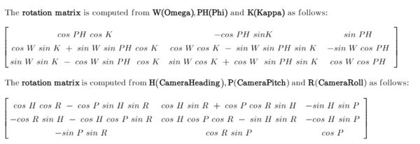
If the values for Omega, Phi, and Kappa are defined, the values for Matrix, CameraHeading, CameraPitch, and CameraRoll will be computed. It is mandatory to follow the sequence Omega, Phi, and Kappa when specifying the values.
Note:
Optional*—The defined FocalLength value will be used only if the affine values (A0,A1,A2 and B0,B1,B2) are also defined. Otherwise, FocalLength will be computed in pixels from the image size and camera field of views.
Recommendations
Oriented imagery supports both approximate and highly precise camera orientations. While many metadata fields are optional, certain fields become essential when higher accuracy is required. These are described below.
Minimum required fields—To load an image into the viewer, the only mandatory fields in an oriented imagery dataset are the camera
X,Ylocation andImagePath. All other required fields are assigned default values as defined in the oriented imagery dataset.The default value for these fields are defined based on the imagery category selected for the first set of images added to the oriented imagery. The imagery categories are Horizonal, Oblique, Nadir, Inspection, and 360 imagery. These defaults are approximations and support general visualization but may not provide suitable world-to-image transformations. For example, with horizontal imagery, the default
CameraPitchfield is set to 90, which is only an approximation. It theCameraPitchvalue is known, it should be defined.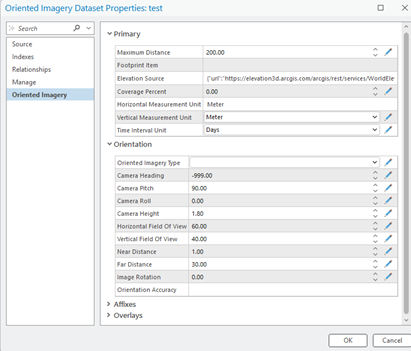
Improving accuracy—To define the viewing frustum and footprint for each image, the following fields are used. They should be defined with suitable accuracy.
-
CameraHeading,CameraPitch, andCameraRolldefine the camera view angles.HorizontalFieldOfViewandVerticalFieldOfViewdefine the camera field of view.CameraHeight,NearDistance, andFarDistancedefine relative height and suitable depth of field.
-
To enhance spatial accuracy, include the following fields:
-
Matrix—Enable more precise definition of camera orientation or it can be determined usingOmega,Phi, andKappaangles.FocalLengthAffine values—
A0,A1,A2andB0,B1,B2RadialandTangentialdistortion coefficientsPrincipalXandPrincipalYcoordinates
-