Create and modify an LRS Network
 Available with the Linear Referencing license.
Each LRS Network is created by combining centerline features with route definitions and attributes. Calibration points are used to apply the measures to routes in the LRS Network. Centerlines and calibration points are registered with the linear referencing system (LRS). You can model the network feature class in advance or create it when you create an LRS Network.
Create an LRS Network
If the network feature class is not created in advance, use the Create LRS Network tool to create it when registering the network with the LRS.
To create an LRS Network, complete the following steps:
In ArcGIS Pro, open the Create LRS Network tool.
Click Browse
 next to Input Location and browse to the geodatabase where you want to create the LRS Network.
Note:
The input workspace must contain an LRS. If the input workspace contains more than one LRS, a drop-down menu appears for you to choose the LRS.
Provide the name of the LRS to which the LRS Network is registered in the LRS Name parameter.
The LRS must reside in the same geodatabase as the Input Location parameter value.
Provide the LRS Network name in the LRS Network Name parameter.
The LRS Network name is also the name of the feature class that is created and registered with the LRS Network.
Note:
The LRS Network name can contain up to 26 characters and cannot contain any special characters other than spaces, hyphens, and underscores.
Accept the default fields or specify the fields for the Route ID Field, From Date Field, and To Date Field parameters.
Optionally, configure a line network or a derived network by doing one of the following:
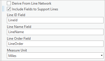
To create an LRS Network that supports lines (line network), check the Include Fields to Support Lines check box and specify the fields for the Line ID Field, Line Name Field, Line Order Field, and Measure Unit parameters.
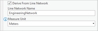
To create a derived network, check the Derive From Line Network check box and specify the line network to which the derived network is registered.
Note:
The default output of this tool is an LRS Network that does not support lines (nonline network), along with a feature class that does not contain the necessary fields to support lines.
Click Run to create the nonline network, line network, or derived network.
Click Run to create the LRS Network.
The LRS Network is created in the specified geodatabase.
Create an LRS Network from an existing dataset
The network feature class can be created before registering the network with the LRS. The spatial reference, tolerance, and resolution settings for the network feature class must align with those of the centerline feature class. The m-tolerance and resolution of the network feature class are determined based on the spatial reference of the centerline feature class, the x,y-tolerance and resolution of the centerline feature class, and the unit of measure of the linear referencing method (LRM).
Use the Create LRS Network From Existing Dataset tool to create an LRS Network in an LRS using an existing polyline feature class. The input feature class cannot be registered with an existing LRS Network. A feature class can only be registered as one LRS Network feature class at a time. If necessary, use the Remove LRS Entity tool to delete the LRS Network to which a feature class is registered.
The Create LRS Network From Existing Dataset tool does not alter the input feature class and adds information to internal metadata tables to register the input feature class as the LRS Network feature class.
To create an LRS Network from an existing dataset, complete the following steps:
In ArcGIS Pro, open the Create LRS Network From Existing Dataset tool.
Click Browse next to LRS Network Feature Class and browse to and choose the input feature class.
The following are the requirements for the input feature class:
The name of the feature class can contain up to 26 characters and cannot contain any special characters other than spaces, hyphens, and underscores.
The feature class must reside in a feature dataset that contains an LRS in the geodatabase.
The name of the feature class is used as the name of the LRS Network.
Click the LRS Name drop-down arrow and choose the LRS name to which the LRS Network is registered.
The LRS must reside in the same geodatabase as the LRS Network feature class.
Click the Route ID Field drop-down arrow and choose the field in the LRS Network feature class to map as the route ID field.
Note:
This field must be a string or GUID field type.
Click the Route Name Field drop-down arrow and choose the string field in the LRS Network feature class to map as the LRS Network route name.
Click the From Date Field drop-down arrow and choose the date field in the LRS Network feature class to map as the start date field.
Click the To Date Field drop-down arrow and choose the date field in the LRS Network feature class to map as the end date field.
Optionally, configure a line network or a derived network by doing one of the following:
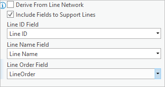
To create an LRS Network that supports lines (line network), check the Include Fields to Support Lines check box and specify the fields for the Line ID Field, Line Name Field, and Line Order Field parameters.
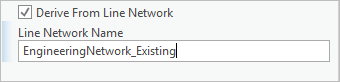
To create a derived network, check the Derive From Line Network check box and provide the LRS Line Network name to which the derived network is registered.
Note:
The default output of this tool is an LRS Network that does not support lines (nonline network), along with a feature class that does not contain the necessary fields to support lines.
Click Run to create the nonline network, line network, or derived network.
Click Run to create the LRS Network.
The LRS Network is created in the same workspace as the LRS Network feature class, and the LRS Network feature class is mapped to the chosen fields.
Modify an LRS Network
You can modify an LRS Network using the Modify LRS Network tool by remapping one or more fields in an LRS Network feature class, such as the route ID, route name, date, and measure fields. Before using this tool, create any fields necessary for field remapping in the underlying LRS Network feature class.
If line support is enabled, the line ID, line name, and line order fields can also be remapped.
To modify an LRS Network, complete the following steps:
In ArcGIS Pro, open the Modify LRS Network tool.
Choose the network feature class you want to modify from the LRS Network Feature Class drop-down list.
The input feature class must represent an LRS Network.
The Route ID Field, Route Name Field, From Date Field, and To Date Field parameters are populated based on the chosen network feature class. If the chosen network feature class is a line network, additional parameters are populated: Line ID Field, Line Name Field, and Line Order Field parameters.
The Route ID Field, From Date Field, and To Date Field parameters are populated based on the chosen network feature class.
Tip:
You can also choose a network feature class by clicking the Browse button
.Optionally, set the Include Fields to Support Lines parameter to Include if you want to configure your network feature class to support lines.
Remap the LRS Network fields as necessary.
Click Run.
The LRS Network fields are remapped.