Construct Sight Lines (3D Analyst Tools)
Summary
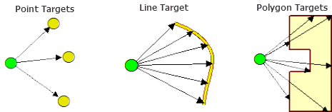
Creates line features that represent sight lines from one or more observer points to features in a target feature class.
Illustration
Usage
Sight lines are sampled from the perimeter of target lines and polygons based on the value specified in the Sampling Distance parameter. The Sampling Distance units should be given in the x-y units of the output feature class.
A join field is used to specify one or more targets for a given observer. If no join field is used, all points will be connected to all targets.
A three-dimensional output will be generated if a height source is specified for both observer and target features. The height source of the observer and target features defaults to the first field name encountered in this list:
Shape.Z(only available for features that are Z-enabled)SpotZZ_ValueHeightElevElevationContour
If no suitable height field exists, the <None> keyword will be used to indicate the features have no Z-values.
If the desired height field does not have a higher priority in the default field selection, the desired field will need to be explicitly specified. Similarly, if a height field is not desired but the feature class contains one of the fields in the default selection list, the <None> keyword will need to be specified.
The following fields will be added to the output feature class that contains the sight lines:
OID_OBSERV—The OID of the observer pointOID_TARGET—The OID of the target featureDIST_ALONG—The distance along the target feature if it is a line or polygon
When the Output The Directions parameter is enabled, the output sight lines will have two additional attribute fields:
AZIMUTH—Degrees from due north where values increase clockwiseVERT_ANGLE—Vertical angle in degrees from horizon where 90° is directly overhead and -90° is directly below. Vertical angle will only be relevant when a height field is specified.
Parameters
| Label | Explanation | Data type |
|---|---|---|
|
Observer Points |
The single-point features that represent observer points. Multipoint features are not supported. |
Feature Layer |
|
Target Features |
The target features (points, multipoints, lines, and polygons). |
Feature Layer |
|
Output |
The output feature class containing the sight lines. |
Feature Class |
|
Observer Height Field (Optional) |
The source of the height values for the observer points obtained from its attribute table. A default Observer Height Field field is selected from among the options listed below by order of priority. If multiple fields exist, and the desired field does not have a higher priority in the default field selection, the desired field will need to be specified.
|
String |
|
Target Height Field (Optional) |
The height field for the target. A default Target Height Field field is selected from among the options listed below by order of priority. If multiple fields exist, and the desired field does not have a higher priority in the default field selection, the desired field will need to be specified.
|
String |
|
Join Field (Optional) |
The join field is used to match observers to specific targets.
|
String |
|
Sampling Distance (Optional) |
The distance between samples when the target is either a line or polygon feature class. The Sampling Distance units are interpreted in the XY units of the output feature class. |
Double |
|
Output The Direction (Optional) |
Specifies whether to add direction attributes to the output sight lines. Two additional fields will be added and populated to indicate direction:
|
Boolean |
|
Sampling Method (Optional) |
Specifies how the sampling distance will be used to establish sight lines along the target feature.
|
String |
Environments
Current Workspace, Extent, Output Coordinate System, Geographic Transformations, XY Resolution, XY Tolerance, Output XY Domain, Z Resolution, Z Tolerance, Output Z Domain, Output CONFIG Keyword, Auto Commit
Licensing information
- Basic: Requires 3D Analyst
- Standard: Requires 3D Analyst
- Advanced: Requires 3D Analyst