Light Signal Clearance Surface (Aviation Tools)
Краткая информация
Creates a Light Signal Clearance Surface (LSCS) based on the FAA Engineering Brief (EB) 95.
A LSCS determines which objects are vertical obstructions. An object is considered a vertical obstruction if it penetrates the LSCS. Surfaces are used to support planning and design activities.
Использование
The Input Runway Features parameter must be z-enabled.
This tool creates the Obstruction Identification Surface (OIS) in an existing polygon or multipatch feature class. It can also be generated in an existing polygon shapefile. If a feature class is specified for the Target OIS Features parameter value, it must have a vertical spatial reference.
OIS tools are flexible and accept a variety of input and output feature class types. For more information, see the OIS Input and Output schemas.
The Input Airport Control Point Feature parameter can be used to supply x-, y-, and z-geometry for displaced threshold features. If displaced thresholds are included, surfaces will be constructed based on their x-, y-, and z-geometry instead of their corresponding runway feature endpoint.
This tool creates an isosceles trapezoid that extends out eight nautical miles from the runway threshold at an angle of -1 degree less than the lowest course signal.
The Start Height parameter default value is 0. When the default value is used, the height will start at the relative runway end's height from the provided Input Runway Features parameter value. If a negative value is provided, the default value will be used.
Примечание:
Any surface that is positioned on a lower elevation than the runway will require manual modification of the final surface of the runway.
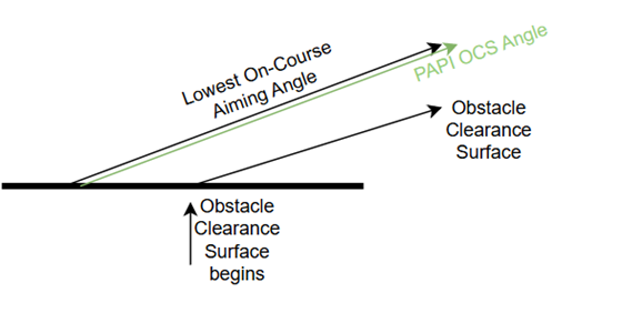
The Precision Approach Path Indicator (PAPI) obstacle clearance surface (OCS) angle for all PAPI lights is equal to the lowest on-course aiming angle -1 degree. The PAPI OCS provides the pilot with a minimum approach clearance.
The following image shows an example of the PAPI OCS angle:
The First PAPI Light and Last PAPI Light parameters refer to the perpendicular distance of the lighting system to the runway centerline. The default First PAPI Light parameter value is 135 feet away from the runway centerline. For more information, refer to the FAA Engineer Brief (EB) 95 and the FAA Advisory Circular 150-5340-30J.
The following image shows an example of PAPI distance values:

Параметры
| Подпись | Объяснение | Тип данных |
|---|---|---|
|
Input Runway Features |
The input runway dataset. The feature class must be z-enabled and contain polylines. |
Feature Layer |
|
Target OIS Features |
The target feature class that will contain the generated OIS. |
Feature Layer |
|
Runway Direction (Дополнительный) |
Specifies the end of the runway where the approach surface will be created.
|
String |
|
Length (Дополнительный) |
The length of the surface in miles. The default value is 8. |
Double |
|
Divergence (Дополнительный) |
The divergence of the surface in degrees. The default value is 14. |
Double |
|
Slope (Дополнительный) |
The slope of the surface in degrees. The default value is 1. |
Double |
|
Distance From Threshold (Дополнительный) |
The distance from the threshold in feet. The default value is 1000. |
Double |
|
First PAPI Light (Дополнительный) |
The distance of the first precision approach path indicator perpendicular to the centerline. The default value is 135. |
Double |
|
Last PAPI Light (Дополнительный) |
The distance of the last precision approach path indicator perpendicular to the centerline. The default value is 225. |
Double |
|
Start Height (Дополнительный) |
The start height of the surface starting at the relative runway end height from the Input Runway Features parameter value. The default value is 0. |
Double |
|
Input Airport Control Point Feature (Дополнительный) |
Supplies x-, y-, and z-geometry for displaced threshold features. If displaced thresholds are included, surfaces will be constructed based on their x-, y-, and z-geometry instead of their corresponding runway feature endpoint. |
Feature Layer |
|
Surface Position (Дополнительный) |
Specifies the position of the PAPI lights on either side of a runway. The position of the PAPI lights will be used to determine the position of the output surface.
|
String |
Производные выходные данные
| Подпись | Объяснение | Тип данных |
|---|---|---|
|
Output OIS Features |
The updated feature class containing the generated OIS. |
Feature Layer |
Параметры среды
Этот инструмент не использует параметры среды геообработки.
Информация о лицензировании
- Basic: No
- Standard: Requires Airports or ArcGIS Aviation Charting
- Advanced: Requires Airports or ArcGIS Aviation Charting