Use the Convert Video Metadata Tool
![]() Available with Image Analyst license.
Available with Image Analyst license.
Geospatial video metadata is the cornerstone for video workflows in ArcGIS . Without accurate metadata the video has little utility beyond viewing. Many metadata files are accurate but have field names and data formats that are not accepted by the video multiplexer. Using the Convert Video Metadata tool, you can easily prepare the metadata file and add correct geospatial context that will be accepted by ArcGIS Pro and ArcGIS Video Server.
Only fields that do not have the correct field names or units need to be converted. Any fields in the metadata that are named correctly and have the correct units and formats will not be changed.
Set up ArcGIS Pro to convert metadata
To convert video metadata, complete the following steps:
Open a new or existing ArcGIS Pro project.
Click the Analysis tab.
Click Tools in the Geoprocessing group.
In the Geoprocessing pane search, or navigate, to Convert Video Metadata tool and click to open.
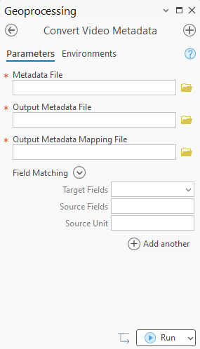
The geoprocessing tool window appears with required fields and field matching input.
Use the Convert Video Metadata metadata tool
For the Metadata File parameter, click the Browse button and select your input
.csvfile.Provide the name for either the Output Metadata File parameter or the Output Metadata Mapping File parameter.
Note:
The Video Multiplexer geoprocessing tool should not be run with both the Output Metadata File and the Output Metadata Mapping File. The mapping file should be used only with the original metadata
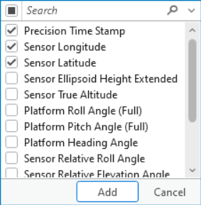
.csv.In the Field Matching parameter, use the Target Fields drop down arrow to select the first field that needs conversion. Alternately, you may click the expansion arrow next to Field Matching header to select multiple fields at once.
Use the the Source Field drop down list to select the appropriate source field. The Source Field list includes all field names in the source
.csvfile.Use the Source Unit drop down list to select the appropriate source unit and format that matches the source
.csvfile.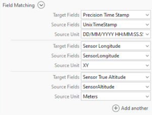
Field matching input that matches Target Fields with Source Fields and Source Units.
Using the table below, continue matching source fields with correspoding fields recognized by Motion Imagery tools. A valid timestamp is the only required field for the tool to run. This timestamp can be in the source .csv or matched in the tool.
The following table lists the Field Name information, such as alias, description, units, and telemetry that is accepted by the video tools in within ArcGIS Pro and ArcGIS Video Server:
Field Name
Alias
Description
Units
Telemetry
Sensor LatitudeDevice LatitudeSensor latitude based on WGS84 ellipsoid that ranges from -90.0 to 90.0.
Degrees
Sensor Location - 2D
Sensor Trail - 2D
Only one timestamp field is required.
Sensor LongitudeDevice LongitudeSensor longitude based on WGS84 ellipsoid that ranges from -180.0 to 180.0.
Degrees
Precision Time StampUnix Time StampCoordinated universal time (UTC).
Microseconds since 1970 (Unix epoch)
Sensor True AltitudeAltitude of sensor as measured from mean sea level (MSL). Elevation values range between -900 meters and 19,000 meters.
Meters
Sensor Location – 3D
Sensor Trail – 3D
Only one field is required for 3D locations.
Sensor Ellipsoid HeightSensor ellipsoid height as measured from the reference WGS84 ellipsoid. Elevation values range between -900 meters and 19,000 meters.
Meters
Sensor Ellipsoid Height ExtendedSensor ellipsoid height as measured from the reference WGS84 ellipsoid. Elevation values range between -900 meters and 40,000 meters.
Meters
Platform Heading AngleAsset (platform) heading relative to true north, measured clockwise in the horizontal plane looking down that ranges from 0 to 360.
Degrees
Platform Pitch AngleAsset (platform) pitch relative to horizontal plane with positive angles for nose above the horizontal plane. Values between -20.0 and 20 are accepted.
Degrees
Sensor Sight Line
Frame Outline (Footprint)
Frame Center (Footprint Centerpoint)
Platform Pitch Angle (Full)Platform PitchAsset (platform) pitch relative to horizontal plane with positive angles for nose above the horizontal plane. Values between -90.0 and 90 are accepted.
Degrees
Platform Roll AngleAsset (platform) roll angle relative to horizontal plane with positive angles for left wing above the horizontal plane. Values between -50.0 and 50 are accepted.
Degrees
Platform Roll Angle (Full)Platform RollPlatform roll angle relative to horizontal plane with positive angles for left wing above the horizontal plane. Values between -90.0 and 90 are accepted.
Degrees
Sensor Relative RollSensor Relative Roll AngleRelative roll angle of sensor to aircraft platform where top of image level is 0 degrees and positive angles are clockwise when looking from behind the camera. Values between 0 and 360 degrees are accepted as integers.
Degrees
Sensor Relative Elevation AngleSensor Relative ElevationRelative angle of sensor pointing direction to the platform horizontal plane where negative angles down. Values between -180 and 180 are accepted.
Degrees
Sensor Relative Azimuth AngleSensor Relative AzimuthRelative angle of sensor pointing direction to platform longitudinal axis as seen from platform that ranges from 0 to 360.
Degrees
Sensor Horizontal Field of ViewSensor Horizontal FOV / Field of View Horizontal / Horizontal FOVHorizontal field of view of selected imaging sensor. Values between 0 and 180 degrees are accepted as integers.
Degrees
Sensor Vertical Field of ViewSensor Vertical FOV / Field of View Vertical / Vertical FOVVertical field of view of selected imaging sensor. Values between 0 and 180 degrees are accepted as integers.
Degrees
Far DistanceSensor Far DistanceThe distance at which targets are far enough away that distance changes no longer meaningfully affect image geometry or focus
Meters
Use the Add another button to create more field matching, until all field names are matched as required.
Note:
Not all fields are required to use Motion Imagery tools in ArcGIS Pro, however, additional metadata fields will allow more functionality.
Click Run.
Note:
If fields in the orignial metadata file are not present in the tool output, they were not recognized or required to use Motion Imagery tools.