Create an Ortho mapping workspace for drone imagery using a geolocation file
![]() Available with Advanced license.
Available with Advanced license.
To create an ortho mapping workspace for processing your drone images, you need two types of information about your drone imagery: the geolocation information and the camera information. This information is commonly stored as metadata in the image files, typically in the EXIF header, and includes latitude, longitude, altitude, and camera type. The camera type is used to compute a camera model based on the specifications of the camera.
Workflow data requirements
The following information is required:
Geolocation and camera model—This information is commonly stored as metadata in the image files, typically in the EXIF header, and includes latitude, longitude, altitude, and camera type. It may also be stored in a text (.txt) file.
DEM—Provides an initial height reference for computing the block adjustment. The global DEM is used by default. For relatively flat terrain, you can specify an average elevation or Z value.
Create an ortho mapping workspace for drone imagery
Use the New Ortho Mapping Workspace wizard to create an Ortho mapping workspace for drone imagery. The wizard serves as a guided workflow, that progresses through three main stages of creating the workspace. The three stages include Workspace Configuration, Image Collection, and Data Loader Options. The Image Collection stage includes the option to incorporate a geolocation file. The stages to create a workspace for drone imagery are detailed in the sections below.
Workspace Configuration
The first stage in creating a Ortho mapping workspace using drone imagery, is configuring the workspace. Follow the steps below to complete the Workspace Configuration stage.
On the Imagery tab, click New Workspace.
On the Workspace Configuration page, type a name for your workspace.
Use the Workspace Type drop-down arrow to choose Ortho Mapping.
For Sensor Data Type select Drone from the drop-down arrow list.
Optionally, use the Basemap drop-down list to choose the basemap you want to use as a backdrop for your image collection.
You can also import and use an existing image collection for your workspace.
Optionally, set the Parallel Processing Factor value of the workspace. The default value of 50% means that half of the total CPU cores will be used to support Ortho mapping processing.
Optionally, check the Track adjustment restore points check box to be able to revert your workspace to a previous state.
Optionally, check the Import and use existing image collection check box to import and use an existing mosaic dataset.
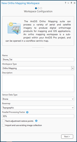
Click Next.
The wizard will advance to the Image Collection page.
Image Collection
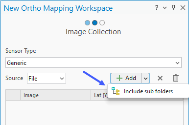
The Image Collection page is where you specify the drone source imagery, define the camera, geolocation information, and spatial referencing.
On the Image Collection page, if working with natural color drone imagery, ensure the Sensor Type is set to Generic. If working with multispectral drone imagery data, choose RedEdge or Altum from the Sensor Type drop-down list.
The drone ortho mapping workspace supports multiple cameras using the generic sensor type. Only the Altum and Micascense Red Edge multispectral sensors are supported. For more information on setting up a workspace for these sensor types, see Create an Ortho Mapping workspace for RedEdge or Altum sensors.
Note:
To support accurate block adjustment, ensure the camera model parameters, such as focal length are accurately defined. In the Image Collection window, the camera model properties can be edited to align the camera parameters with the manufacturer’s specifications
For Source ensure File is selected. If you want to provide a folder instead of listing all images, you can click Folder from Source drop-down menu.
Click the Add button to browse to a folder, and load the drone imagery for the project. If the images are in subfolders, click the Add images drop-down menu and select Include Sub folders option.
Make sure images in one folder are captured by the same camera. The camera can be different for different folders. Also make sure the folder provided contains images, or a warning will be displayed and the Next button will be greyed out.
Note:
If the images are stored in a cloud environment, it is recommended that the Folder option be used as the Source. This is to improve the data loading speed over the network.
For Geolocation click the Import button
 to open the Import Geolocation window.
Note:
If the images in your collection do not contain an EXIF header, provide a Geolocation GPS text file, such as a comma-separated value (
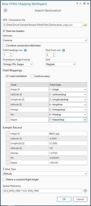
.csv) file, which includes values for the fields:Image Name,Latitude,Longitude, andAltitude, and optionally,Omega,Phi, andKappa, or Roll, Pitch, and Yaw. The geolocation file should have been provided by your vendor with the drone imagery.In the Import Geolocation window, for the GPS/Orientation file, click the Browse button to navigate and select the GPS text file on disk, then click OK.
Set the appropriate Delimiter value.
For the Field headings row, specify the row number where the field headings for the exterior orientation parameters begin. You may need to make a copy of and open the GPS file to determine the row number.
Note:
You may need to make a copy of the GPS file, then open it to determine the row number.
For Start from row, specify the row number where the exterior orientation parameters begin.
Select the appropriate Orientation Angle Format value and Unit from the drop-down list.
Map the exterior orientation data fields appropriately using the options in the Field Mappings section.
Review the accuracy of the field mappings in the Sample Record section.
Click OK to accept the changes. You will be returned to the Image Collection pane in the wizard.
Optionally, edit the altitude reference of your image collection, click the Edit button
 next to the Geolocation information. For Z Value Type, select Flight Height if your drone reports heights relative to the takeoff point, or Altitude for heights relative to a vertical datum. Click OK to save the settings on the Edit Geolocation Reference page.
Note:
Z values are typically recorded as heights above a vertical datum or heights relative to the drone takeoff point.
Click OK to accept the changes. You will be returned to the Image Collection pane in the wizard.
Optionally, click the Spatial Reference button
 to select a map reference system and vertical coordinate system.
Note:
Spatial Reference is automatically populated with the GPS location from your data. The coordinate systems of the workspace are used in the map, resulting orthomosaic, and DEM.
If the camera type is missing from the EXIF header information, or a warning sign is visible in the Cameras section, click the properties button
 to open the Edit Camera Parameters page and select Camera Maker and Camera Model values.
Once you select the camera make and model, the wizard completes the form based on the extensive database of supported cameras and computes the camera model, also known as the interior orientation. If your camera is not supported, you can enter the camera information on the Edit Camera Parameters page and save it. The camera parameters setting is used to compute the camera model.
Note:
Only values for Focal length (mm) and Pixel Size on the Sensor (in mm) are required to compute the camera model. These values can often be found in the image properties, although in some cases, they are missing. In this case, the Pixel Size on the Sensor value is estimated automatically for the 35 mm equivalent focal length for supported camera models using the equations below:
\(Pixel \space Size \space = \space CCD \space Diagonal \space / \space Image \space Diagonal(in \space pixels)\)
where
\(CCD \space Diagonal \space = \space 2 \space * \space (Focal \space Length \space * \space Tan(FOV/2))\)
If this value is not automatically calculated, click the Pixel Size on the Sensor button
and choose Field of view (FOV), 35 mm equivalent focal length, or Dimension on the Sensor Specification drop-down menu. Enter the corresponding specifications for your camera model and click OK. The value for Pixel Size on the Sensor should now be populated.Choose the correct Camera File option with the camera model information.
This can be a
.camfile or a.csvfile. If neither is available, you can manually enter the camera parameters on this page.Click the Back button to return to the Image Collection page.
Click Next to accept the changes.
The wizard will advance to the Data Loader Options page.
Data Loader Options
The Data Loader Options page is where you specify the Elevation Source, Advanced Options, and Pre-processing options.
On the Data Loader Options page, under Elevation Source, choose DEM.
Set Elevation Source.
If you have access to the internet, use the default elevation service for the DEM parameter and Average Elevation from DEM for the Elevation Source option.
If you do not have access to the internet, provide a DEM file covering the project area and choose Average Elevation for the Elevation Source option.
If you do not have access to the internet or a DEM, choose the Constant Elevation option from the drop-down menu and enter an elevation value for the project area. This value can be determined from a topographic map in ArcGIS Online. The elevation is only used to provide an initial estimate of the flight height for each image.
Optionally, adjust the Image Exclusion Height value.
Images having a flight height above the terrain that is less than the specified value are not included in the workspace.
Expand the Advanced Options section to expose additional settings.
Optionally, edit the Band Combination parameters if you want to reorder the band combination from the default order.
Accept all other defaults and click Finish to create the workspace.
When the ortho mapping workspace is created, the image collection is loaded in the workspace and displayed on the map. You are now ready to perform adjustments and generate ortho products.
Drone imagery tutorial
For a guided tutorial on the full drone imagery workflow, see Create Drone Imagery Products.