Mesh Editing using ArcGIS Reality for ArcGIS Pro
![]() Available with Standard or Advanced license.
Available with Standard or Advanced license.
![]() Available for an ArcGIS organization with the ArcGIS Reality license.
Available for an ArcGIS organization with the ArcGIS Reality license.
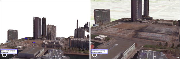
ArcGIS Reality for ArcGIS Pro enables the generation of 2.5D and 3D meshes from airborne imagery to support your projects. These meshes are a textured model of the project area which transforms your 2-dimensional imagery into photo-realistic representations of your project area. The quality of the generated mesh can sometimes be adversely impacted by various imagery related factors, such as temporal differences, poor image quality, highly reflective surfaces and insufficient imagery overlap. These may result in spikes, incomplete or warped facades and surfaces which degrade the mesh quality.
Most of the identified issues can be addressed satisfactorily using a correction polygon. A correction polygon is 3D shapefile (for DSM mesh edits) or 3D multipatch feature class (for 3D mesh edits) that identifies the area to be edited. The correction polygon can be a single-part or multi-part polygon having the same spatial reference as the project being edited. The correction polygon is input into the product generation wizard, which regenerates the affected region.
Note:
The following needs to be considered when editing 2D and or 3D products. If multiple products (2D and 3D) were generated concurrently, the same 3D multipatch feature file needs to be used as a correction polygon for both types of data. The multipatch feature file is created in Scene View. If only 2D products were generated, a 3D shapefile is recommended as a correction polygon. The 3D shapefile can be generated either in Scene View, or a Map View.
Workflows describing the correction of meshes and regeneration of products are addressed below.
Editing errors in a 2.5D or DSM Mesh
In a 2.5D or DSM mesh, the errors are primarily in the horizontal plane or on the horizontal surface. Common errors may include spikes, wavy surfaces, and floating objects.
To correct anomalies in a DSM mesh, perform the following steps, which assume a DSM mesh product was already generated.
Add the DSM mesh product to a local Scene Viewer
In the Catalog pane, expand the Reality Mapping container housing your workspace.
Locate and expand the workspace containing the product to be edited.
Expand both the Products folder and the Meshes folder.
Expand the DSM Mesh folder and the SLPK folder.
Right-click on
DSM_Mesh.slpk, select Add to New > Local Scene from the drop-down list. A new scene viewer will be added to the map view with the mesh product loaded in the map.Roam and zoom to the area to be edited.
Create a 3D polygon to be used as a correction feature
Right-click on the folder to store the correction feature, and select New > Shapefile.
The Create Feature Class pane will open.
Type a name for Feature Class Name parameter.
Ensure Geometry Type is Polygon.
For the Has Z parameter, select Yes.
For the Coordinate System parameter, click the drop-down list and select
Current Map [Scene_*your file name*].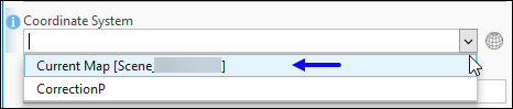
Accept all other defaults and click Run to create the correction feature. The correction feature will be added to the Scene view when completed.
Perform 2D heads-up digitizing to define the area to correct
2D heads-up digitizing can be done either from the 2D map or scene viewer. The viewer chosen needs to be dictated by the error to be corrected. For example, if correcting spikes in the DSM mesh, digitizing from the scene viewer is recommended as it depicts the spike location more clearly. If regularizing a building shape, the 2D map with the aide of a true ortho is recommended.
To digitize a polygon identifying the area to be corrected, perform the following steps:
Within the Scene Viewer, optionally change the symbology of the correction feature in the Symbology pane to make it hollow.
Making the feature hollow will eliminate the chance of the fill obscuring other features during the digitizing process.
Define your elevation source. In the Edit menu, Elevation group, define the source of the elevation values to be added to the correction feature by using the Choose how to add Z tool.
Within this tool there are two Mode options for defining your elevation source, Surface and Constant Z. In Scene Viewer, only the Constant Z option is available.
- Click Mode > Constant Z from the drop-down list. Enter the Constant Z value in the input box and ensure the correct unit is defined in the unit picker.
Note:
Constant Z is appropriate in scenarios where the terrain is flat and the terrain elevation value is known, the terrain height can be defined as the elevation to be applied to the correction feature.
Note:
Surface—Uses a DEM as the elevation source. A DEM is defined as the correction feature elevation source only when digitizing from the 2D map. Optionally, a preferred DEM layer can be added.
In the Contents pane, select the name of the correction feature created earlier.
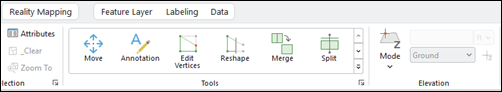
On the Edit tab, within the Features group, click the Create button.
The Create Features pane will open.
Under the Templates tab, click on the correction feature created earlier.
Ensure Create a polygon feature
 template is selected.
Begin to trace the boundary of the area to be corrected. Double-click in the viewer or select F2 when finished.
On the Edit tab, in the Manage Edits group, click Save to save your edits.
Use the Correction Features in the product generation wizard
Follow the steps below to correct the 2.5D mesh in the Product generation wizard.
On the Reality Mapping tab, within the Product group, select the option initially used to create the product being edited. For example, if multiple products were initially created using the Multiple Product wizard, the same wizard needs to be selected with the same product options as initially selected.
Click Shared Advanced Settings.
The Advanced Product Settings window opens with settings from the previous run of the tool automatically populated.
For Correction Features, select the polygon created earlier that identifies the area to be corrected.
Note:
If both the Correction Polygon and Waterbody Feature polygon are specified, where they overlap, the Waterbody Feature will take precedence in processing and the correction polygon ignored.
Define the location of the Processing Folder to be on a fast disk with sufficient available storage.
Accept all other defaults and click OK to accept changes and close the Advanced Product Settings window.
You will be returned to the Product Generation Settings window.
Complete the wizard with settings matching those from the initial product generation process.
Product settings from the initial Reality processing should still be present.
Upon completing the settings in the wizard, click Finish.
Once processing is complete, review the area corrected for completeness.
Editing errors in a 3D Mesh
Use the following as a guide to correct anomalies in a 3D mesh. The following steps assume a 3D mesh product was already generated.
Add the 3D mesh to a local Scene Viewer
Follow the steps below to add a 3D mesh to Scene Viewer.
In the Catalog pane, expand the Reality Mapping container storing your workspace.
Locate and expand the workspace containing the product to be edited.
Expand both the Products folder and the Meshes folder.
Expand the 3D Mesh folder and the SLPK folder.
Right-click on
Mesh.slpkand select Add to New > Local Scene from the drop-down list.A new scene viewer will be added to the map view with the mesh product loaded.
A new scene viewer will be added to the map view with the mesh product loaded.
Roam and zoom to the area to be edited.
Create a 3D multipatch polygon to be used as a correction feature
Follow the steps below to create a 3D multipatch polygon to be used as a correction feature.
Right-click on the folder to store the correction feature, and select New > Shapefile.
The Create Feature Class pane will open.
Type a name for the Feature Class Name parameter.
Ensure the Geometry Type parameter is set to Multipatch.
For Coordinate System, click the drop-down list and select
Current Map [Scene_*your file name*].Accept all other defaults and click Run to create the correction feature. The correction feature will be added to the Scene view when completed.
Change the symbology of the created 3D multipatch correction feature
Follow the steps below to change the symbology of the created 3D multipatch polygon to enhance interpretability.
In the Contents pane, click the 3D multipatch symbol.
The Format Mesh Symbol window will open.
Click the Properties tab.
The Properties dialog will open.
For Color, click the drop-down menu to select from the available options.
For Outline Color, click the drop-down menu and select an option that offers good contrast with the color selected above.
Click Apply at the bottom of the window to accept changes.
Perform 3D heads-up digitizing for the Correction Feature
To digitize a polygon identifying the area to be corrected, perform the following steps:
In the Contents pane, select the name of the correction feature created earlier.
On the Edit tab, click Create, located within the Features group.
This will open the Create Features pane.
Under the Templates tab, click on the correction feature created earlier.
Ensure “Create 3D Geometry”
 template is selected.
Begin to trace the boundary of the anomaly to be corrected. Select F2 when finished. On the Edit tab, within the Manage Edits group, click Save to save your edits.
Note:
After digitizing the first point and moving to the second, the line may automatically snap arbitrarily to a vertex on the mesh. To turn off snapping while digitizing, press the spacebar on the keyboard.
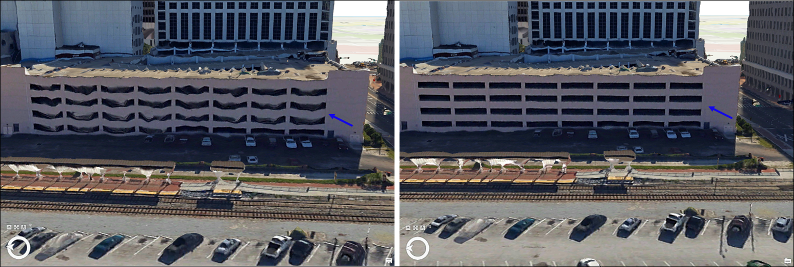
Digitize as many areas as you deem necessary to achieve your correction objective.
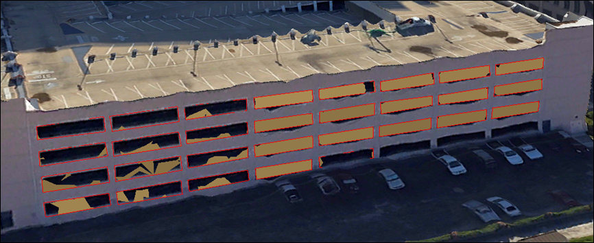
Note:
Each feature to be corrected needs to be collected separately. For example, in the graphic above, each window opening is digitized as a separate entity comprising the multipatch polygon, rather than digitizing the entire building facade in one polygon.
When all areas to be corrected are digitized, save your edits.
Use the Correction Features in the product generation wizard
Follow the steps below to correct the 3D mesh in the Product generation wizard.
On the Reality Mapping tab, within the Product group, select the option initially used to create the product being edited. For example, if multiple products were initially created using the Multiple Product wizard, the same wizard needs to be selected with the same product options as initially selected.
Click Shared Advanced Settings.
The Advanced Product Settings window opens with settings from the previous run of the tool automatically populated.
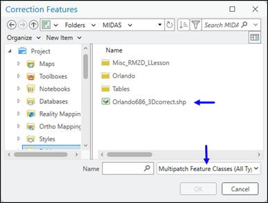
For Correction Features, select the polygon created earlier that identifies the area to be corrected.
Note:
If navigating to disk to select the 3D multipatch, you may need to change the Correction Features window filter to see the multipatch in File Explorer.
Note:
If both the Correction Polygon and Waterbody Feature polygon are specified, where they overlap, the Waterbody Feature will take precedence in processing and the correction polygon ignored.
Define the location of the Processing Folder to be on a fast disk with sufficient available storage.
Accept all other defaults and click OK to accept changes and close the Advanced Product Settings window.
You will be returned to the Product Generation Settings window.
Complete the wizard with settings matching those from the initial product generation process.
Product settings from the initial Reality processing should still be present.
Upon completing the settings in the wizard, click Finish.
Once processing is complete, review the area corrected for completeness.