Create a template for an LRS route log data product
 Available with the Linear Referencing license.
You can use the Data Product Designer wizard to create a template for a linear referencing system (LRS) route log data product.
The following table shows a sample route log created for the Dripping Springs to Smithville 300 engineering route depicted in the following diagram. The measures on the route increase in the direction of the arrow. The route log places the records on the route as if a person moving in the direction of the arrow is noting the pipe characteristics and measure value information of the specified layers as they are encountered.

The route log data product returns the location and information of point events, line events, intersections, referent features, and polygon boundaries for the Dripping Springs to Smithville 300 engineering route. The following list shows the characteristics found along the route:
Log fields: Anomaly Type, Coating Material, Operating Pressure, and Crossing Utility Intersection
Location fields: Operating Area and City boundaries
Referent field: Stationing Marker
The following table is the returned route log for the route after inputting the LRS data template into the Generate LRS Data Product tool.
| Route Name | Description | Measure | Referent | Offset | Operating Area | City | Anomaly Type | Intersection | Coating Material | Operating Pressure |
|---|---|---|---|---|---|---|---|---|---|---|
| Dripping Springs to Smithville 300 | Begin Pipe: Dripping Springs to Smithville 300 | 0 | 00+00.00 | 0 | SW | Roxton | Copper | 500 | ||
| Dripping Springs to Smithville 300 | Intersecting Dripping Springs to Smithville 300, Pipe013S | 0 | 00+00.00 | 0 | SW | Roxton | Dripping Springs to Smithville 300, Pipe013S | Copper | 500 | |
| Dripping Springs to Smithville 300 | Begin Copper coating | 0 | 00+00.00 | 0 | SW | Roxton | Copper | 500 | ||
| Dripping Springs to Smithville 300 | Begin Operating Pressure 500 PSI | 0 | 00+00.00 | 0 | SW | Roxton | Copper | 500 | ||
| Dripping Springs to Smithville 300 | Dent | 1200 | 00+00.00 | 1200 | SW | Roxton | Dent | Copper | 500 | |
| Dripping Springs to Smithville 300 | Intersecting Dripping Springs to Smithville 300, Pipe336N | 1200 | 00+00.00 | 1200 | SW | Roxton | Dripping Springs to Smithville 300, Pipe336N | Copper | 500 | |
| Dripping Springs to Smithville 300 | Leaving City Limit: Roxton | 1500 | 10+50.00 | 0 | SW | Roxton | Copper | 500 | ||
| Dripping Springs to Smithville 300 | Entering City Limit: Dean | 1500 | 10+50.00 | 0 | SW | Dean | Copper | 500 | ||
| Dripping Springs to Smithville 300 | End Operating Pressure 500 PSI | 2000 | 10+50.00 | 500 | SW | Dean | Copper | 500 | ||
| Dripping Springs to Smithville 300 | Begin Operating Pressure 350 PSI | 2000 | 10+50.00 | 500 | SW | Dean | Copper | 350 | ||
| Dripping Springs to Smithville 300 | Gouge | 2300 | 10+50.00 | 800 | SW | Dean | Gouge | Copper | 350 | |
| Dripping Springs to Smithville 300 | Internal Corrosion | 2500 | 10+50.00 | 1000 | SW | Dean | Internal Corrosion | Copper | 350 | |
| Dripping Springs to Smithville 300 | End Copper coating | 3000 | 10+50.00 | 1500 | SW | Dean | Copper | 350 | ||
| Dripping Springs to Smithville 300 | Begin Steel coating | 3000 | 10+50.00 | 1500 | SW | Dean | Steel | 350 | ||
| Dripping Springs to Smithville 300 | Intersecting Dripping Springs to Smithville 300, Pipe912N | 3650 | 30+20.00 | 300 | SW | Dean | Dripping Springs to Smithville 300, Pipe912N | Steel | 350 | |
| Dripping Springs to Smithville 300 | End Operating Pressure 350 PSI | 4500 | 45+00.00 | 0 | SW | Dean | Steel | 350 | ||
| Dripping Springs to Smithville 300 | End Steel coating | 4500 | 45+00.00 | 0 | SW | Dean | Steel | 350 | ||
| Dripping Springs to Smithville 300 | End Pipe: Dripping Springs to Smithville 300 | 4500 | 45+00.00 | 0 | SW | Dean | Steel | 350 |
Other types of route log data products that you can configure include the following:
Change of operating conditions along pipes in different operating areas
In-line Inspection (ILI) survey reading, document point, and ILI range along pipes with markers as the referent location
The measure of intersections between a pipe and features such as hydrology units, transportation lines, utility lines, other pipelines, and operating area boundaries
The following table shows a sample route log created for the SR9WB route depicted in the following diagram. The measures on the route increase in the direction of the arrow. The route log places the records on the route as if a person moving in the direction of the arrow is noting the classification and measure value information of the specified layers as they are encountered.

The route log data product returns the location and information of point events, line events, intersections, referent features, and polygon boundaries for the SR9WB route. The following list shows the characteristics found along the route:
Log fields: Sign Type, Functional Class, Speed Limit, and Intersection
Location fields: County and City boundaries
Referent field: Mile post
The following table is the returned route log for the route after inputting the LRS data template into the Generate LRS Data Product tool.
| Route ID | Description | Measure | Referent | Offset | County | City | Sign Type | Intersection | Functional Class | Speed Limit |
|---|---|---|---|---|---|---|---|---|---|---|
| SR9WB | Begin Route: SR9WB | 0 | Mile 0 | 0 | Union | Titan | Interstate | 65 | ||
| SR9WB | Intersecting SR9WB, SW26WB | 0 | Mile 0 | 0 | Union | Titan | SR9WB, SW26WB | Interstate | 65 | |
| SR9WB | Begin Functional Class Interstate | 0 | Mile 0 | 0 | Union | Titan | Interstate | 65 | ||
| SR9WB | Begin Speed Limit 65 MPH | 0 | Mile 0 | 0 | Union | Titan | Interstate | 65 | ||
| SR9WB | Speed Limit Sign | 1.4 | Mile 0 | 1.4 | Union | Titan | Speed Limit | Interstate | 65 | |
| SR9WB | Stop Sign | 2.5 | Mile 2 | 0.5 | Union | Titan | Stop | Interstate | 65 | |
| SR9WB | Intersecting SR9WB, NR38WB | 2.5 | Mile 2 | 0.5 | Union | Titan | SR9WB, NR38WB | Interstate | 65 | |
| SR9WB | Leaving City Limit: Titan | 3.5 | Mile 2 | 1.5 | Union | Titan | Interstate | 65 | ||
| SR9WB | Entering City Limit: Adam | 3.5 | Mile 2 | 1.5 | Union | Adam | Interstate | 65 | ||
| SR9WB | End Functional Class Interstate | 4 | Mile 2 | 2 | Union | Adam | Interstate | 65 | ||
| SR9WB | Begin Functional Class Local | 4 | Mile 2 | 2 | Union | Adam | Local | 65 | ||
| SR9WB | End Speed Limit 65 MPH | 6 | Mile 6 | 0 | Union | Adam | Local | 65 | ||
| SR9WB | Begin Speed Limit 40 MPH | 6 | Mile 6 | 0 | Union | Adam | Local | 40 | ||
| SR9WB | Speed Limit Sign | 7.6 | Mile 6 | 1.6 | Union | Adam | Speed Limit | Local | 40 | |
| SR9WB | End Speed Limit 40 MPH | 10 | Mile 10 | 0 | Union | Adam | Local | 40 | ||
| SR9WB | End Functional Class Local | 10 | Mile 10 | 0 | Union | Adam | Local | 40 | ||
| SR9WB | Intersecting SR9WB, NR71WB | 10 | Mile 10 | 0 | Union | Adam | SR9WB, NR71WB | Local | 40 | |
| SR9WB | End Route: SR9WB | 10 | Mile 10 | 0 | Union | Adam | Local | 40 |
Other types of route log data products that you can configure include the following:
Change of pavement conditions along routes in different urban areas
Crash, speed limit, and intersections along routes with signs as the referent location
The entry and exit measures of interstate routes when they cross counties and cities
The next sections describe how to use the Data Product Designer wizard to create a template for the Generate LRS Data Product tool to produce a route log data product similar to the one shown in the table above.
Choose an LRS data product type
The first step in the Data Product Designer wizard is to specify the data product type.
To specify the Route Log data product type, complete the following steps:
Start ArcGIS Pro and open a project with LRS data in the map.
On the Linear Referencing tab, in the Data Products group, click Data Product Designer
 .
The Choose an LRS data product type page of the Data Product Designer wizard appears.
Click the Data Product Type drop-down arrow and choose Route Log.
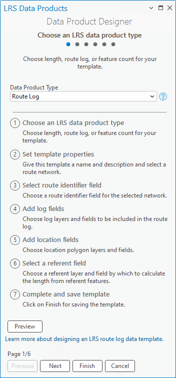
Click Next.
The Set template properties page appears.
Set template properties
To set the template properties once the template type is specified, complete the following steps:
Provide a template name.
By default, the template is saved in the project folder. Optionally, browse to a different location, provide a name for the template, and click OK.
Click the Network drop-down arrow and choose a network.
Route characteristics are provided for this network when the Generate LRS Data Product tool is run with the template.
Optionally, provide a description.
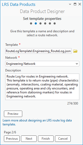
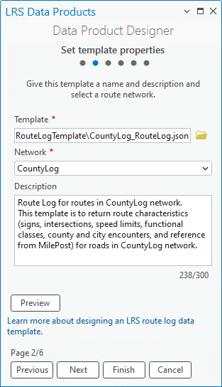
Optionally, click Preview to preview the information on a canvas.


Note:
If the chosen network is a line network, the Line Name column appears in the route log next to the route identifier field.
Click Next.
The Select a route identifier field page appears.
Select a route identifier field
The next step to produce a template for a route log is to add a route identifier field and provide informative text. The route identifier can be a route name or route ID.
This example uses Route Name as the engineering network's route identifier field and Route Name as the display name in the Name in Table text box, which also updates the display name on the preview canvas. In the example route log, the start and end points of a route are Begin Pipe: Dripping Springs to Smithville 300 and End Pipe: Dripping Springs to Smithville 300, respectively.
This example uses ROUTE_ID as the network's route identifier field and Route ID as the display name in the Name in Table text box, which also updates the display name on the preview canvas. In the example route log, the start and end points of a route are Begin Route: SR9WB and End Route: SR9WB, respectively.
To specify a route identifier field, complete the following steps:
Click the Route Identifier drop-down arrow and choose a field.
The default value is Route ID if the specified network is not a line network, or Route Name if the specified network is a line network.
If the specified network has both a route ID and a route name configured, you can choose one of the two options using the drop-down arrow.
Optionally, update the display name in the Name in Table text box.
The default display name is the Route Identifier value.
Optionally, update the text in the Feature Begin Text and Feature End Text text boxes to indicate the start and end of the routes.
The default values are Begin and End, respectively.
Optionally, provide text in the Field Value Prefix and Field Value Suffix text boxes to supplement information before and after the route identifier value, respectively.
In the example, Pipe: is the prefix for the route identifier value. The example does not include a field value suffix.
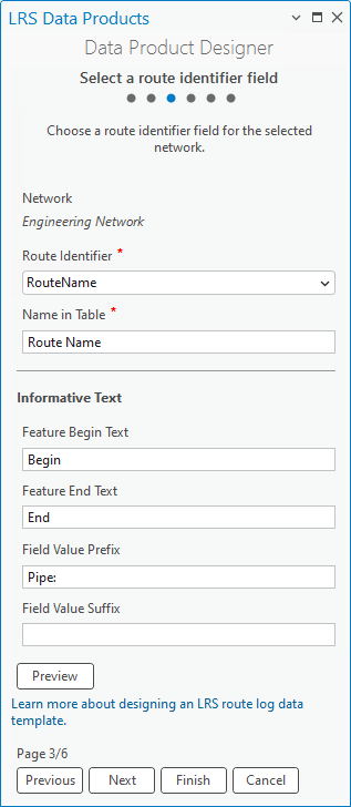

In the example, Route: is the prefix for the route identifier value. The example does not include a field value suffix.
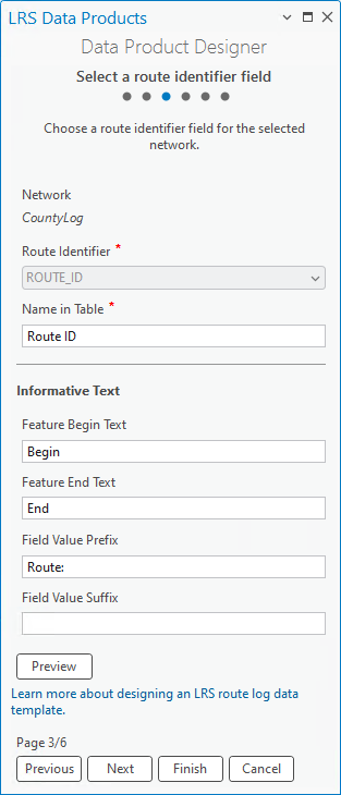

Choosing a route identifier field ensures that the route log data product generated using this template includes route information fields.


Click Next.
The Add log fields page appears.
Add log fields
In a route log data product, the log fields form the columns that include event and intersection information. You can add log fields from log layers and supplement informative text. Informative text provides details about the log layers.
Note:
You can also use a centerline feature class as a log layer when you configure it with the Address Data Management solution or a utility network.
The example in this section uses four log layers:
Anomaly point event
Crossing Utility intersection
Coating line event
Operating Pressure line event
Signs point event
Intersection
Speed Limit line event
Functional Class line event
An LRS route log data product generated using this template returns a record when any of these layers appear and end on a route.
Note:
Adding log fields is optional. If you don't want to add log fields to the template, click Next to proceed to adding location fields.
To add log fields, complete the following steps:
Click Add to create a blank row in the Log Fields parameter.
Click the Layer drop-down arrow and choose a log layer.
The layer can be a point event, a line event, or an intersection that is registered to the network specified when setting the template properties. It must be stored in the same geodatabase or feature service and have the same coordinate system as the specified network. The layer you specify determines which fields are available for the Field menu.
The first log layer configured in the example is the Anomaly point event.
The first log layer configured in the example is the Signs point event.
Click the Field drop-down arrow and choose a field from the layer specified.
For this example, Anomaly Type is configured as one of the log fields.
For this example, Sign Type is configured as one of the log fields.
Optionally, update the display name in the Name in Table text box.
The default display name is the Field value.
This text updates the row in the Log Fields parameter.
Optionally, provide text in the Feature Begin Text and Feature End Text text boxes.
This text appears before the start and end of log fields.
The default values are Begin and End, respectively.
Note:
The Feature Begin Text and Feature End Text text boxes are not available when using a point event layer or an intersection layer.
Optionally, provide text in the Field Value Prefix and Field Value Suffix text boxes.
This text provides additional information about the log value and is inserted before and after the log value, respectively.
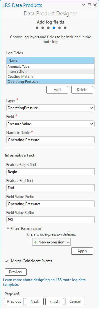
In the following example, Operating Pressure is the Field Value Prefix value and PSI is the Field Value Suffix value added for the Operating Pressure line event.
In the following example, Speed Limit is the Field Value Prefix value and MPH is the Field Value Suffix value added for the Functional Class line event.


Optionally, click New expression under Filter Expression and define an expression that filters specific log values.
The route log returns only features that meet the filter expression. For example,
COATING_MATERIAL <> 'Plastic'returns nonplastic coating material events.The route log returns only features that meet the filter expression. For example,
FUNCTIONAL_CLASS = 1returns only interstate functional classes.Optionally, check the Merge Coincident Events check box for line event log layers.
Checking this box returns coincident events with the same value in the log field as a single event in the route log.
To add multiple log fields, repeat the previous steps for each field.
For this example, Anomaly Type, Intersection, Coating Material, and Operating Pressure are configured as log fields.

For this example, Sign Type, Intersection, Speed Limit, and Functional Class are configured as log fields.
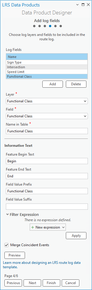

By adding log fields, route log data products generated with this template have columns that include event and intersection information.


Click Next.
The Add location fields page appears.
Add location fields
After adding log layers, you can add location layers and location fields. The location fields form the columns that contain information about the polygon boundaries crossed by the routes. You can also provide informative text for the location layers.
The example in this section uses Operating Area and City as the location layers. A route log data product generated using this template returns a record when a route enters or leaves an operating area or city.
The example in this section uses County and City as the location layers. A route log data product generated using this template returns a record when a route enters or leaves a county or city.
Note:
Adding location fields is optional. If you don't want to add location fields to the template, click Next to proceed to selecting a referent field.
To add location fields, complete the following steps:
Click Add to create a blank row in the Location Fields section.
Click the Layer drop-down arrow and choose a location layer.
The layer must be a polygon feature class stored in the same geodatabase or feature service and have the same coordinate system as the specified network when setting the template properties.
The first location layer configured in the example is Operating Area.
The first location layer configured in the example is County Boundary.
Click the Field drop-down arrow and choose a field from the location layer specified.
For this example,
Operating Areais configured as the location field.For this example,
Countyis configured as the location field.Optionally, update the display name in the Name in Table text box.
The default display name is the location field.
This text updates the row in the Location Fields parameter.
Optionally, provide text in the Feature Begin Text and Feature End Text text boxes.
This text appears before the start and end of the location fields.
The default values are Begin and End, respectively.
For this example, the Feature Begin Text and Feature End Text text boxes are updated with
Entering Operating Area Limit:andLeaving Operating Area Limit, respectively.For this example, the Feature Begin Text and Feature End Text text boxes are updated with
Entering County Limit:andLeaving County Limit:, respectively.Optionally, click the Filter Expression drop-down arrow and provide an expression to filter by a specific location field.
The route log returns only features that meet the filter expression.
The example does not have a filter expression configured for location fields. One example of a filter expression,
REGION = "S-US", returns only route interactions with operating areas in the Southern United States.The example does not have a filter expression configured for location fields. One example of a filter expression,
REGION = "SOUTHWEST", returns only route interactions with counties in the southwest region.To add multiple location fields, repeat the previous steps for each field.
The example has two location fields: Operating Area and City.
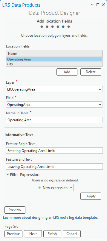

The example has two location fields: County and City.
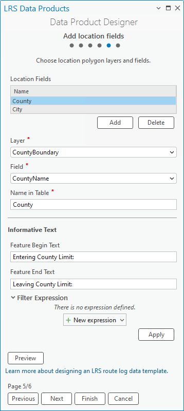

By adding location fields, the route log data products generated with this template have columns that include records of when a route enters or leaves a location.


Click Next.
The Select a referent field page appears.
Select a referent field
After adding location layers, you can add a referent field from a referent layer. The referent field forms the columns that include referent and offset information. You can also provide informative text for the referent layer.
Note:
Configuring a referent field is optional. If you do not want to configure a referent field, click Finish to save the template.
You can configure only one referent layer for a route log template.
To configure a referent field, complete the following steps:
Click the Referent Located At drop-down arrow and choose a referent method:
Nearest Upstream—The nearest referent feature upstream of the route log entry is used to calculate the referent offset. If no upstream referent feature exists, the referent values are empty.
Nearest—The nearest referent feature, upstream or downstream to the route log entry, is used to calculate the referent offset.
The following image and table illustrate the difference between the two referent methods. The dent anomaly is 1,000 feet upstream from the nearest stationing marker, so the offset is -1000. Additionally, the dent anomaly is 6,000 feet from the nearest upstream stationing marker, so the offset is 6,000.

Referent method Referent Offset (US Survey Feet) Nearest 70+00.00 -1000 Nearest Upstream 00+00.00 6000 The following image and table illustrate the difference between the two referent methods. The stop sign event is 1 mile upstream from the nearest mile post, so the offset is -1. Additionally, the stop sign is 6 miles from the nearest upstream mile post, so the offset is 6.

Referent method Referent Offset (US Survey Miles) Nearest Mile 7 -1 Nearest Upstream Mile 0 6 Click the Layer drop-down arrow and choose a referent layer.
The layer must be a point event or intersection stored in the same geodatabase or feature service and have the same coordinate system as the specified network when setting the template properties.
For this example, Stationing Marker is configured as the referent layer.
For this example, Mile Post is configured as the referent layer.
Click the Field drop-down arrow and choose a referent field.
For this example,
Stationis the referent field.For this example,
Post_Nameis the referent field.Optionally, update the display name in the Name in Table text box.
The default display name is Referent.
Optionally, provide text in the Field Value Prefix and Field Value Suffix text boxes.
The text provides information about the referent value and is inserted before and after the value, respectively.
Optionally, click the Offset Unit drop-down arrow and choose a different unit.
The default offset unit is Feet (International).
For this example, the Offset Unit value is set to Feet (US Survey).


For this example, the Offset Unit value is set to Miles (US Survey).
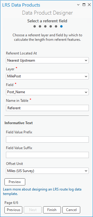

By adding a referent field, the route log data products generated with this template have columns that include referent and offset information.


Click Finish to save the template.
You can use the completed template in the Generate LRS Data Product tool to generate an LRS data product.
Note:
To review or edit an existing template, on the Set template properties page, click Browse for the template location  next to the Template text box. You can choose a template from the project folder or from other locations.