Manage address and roadway characteristic data together
 Available with the Linear Referencing license.
ArcGIS Linear Referencing allows you to manage and maintain address and roadway characteristic data in a linear referencing system (LRS) with a common geodatabase. ArcGIS Linear Referencing can be configured out of the box with the Address Data Management solution in a single geodatabase by including address range fields from the Address Data Management solution in a feature class that also serves as the ArcGIS Linear Referencing centerline feature class. You can also support address data in a customized fashion by modeling address information on either the LRS centerline or LRS line event. In both the Address Data Management solution configuration and the custom data model configuration, you must configure a feature class with site address points with the LRS.
In ArcGIS, you can use the Address Data Management solution to maintain and improve an authoritative address repository. The solution contains a set of capabilities designed to help maintain, improve, and share address information in support of services and commerce within a community, such as E911, permitting, and assessment.
The following sections describe how to model address information in conjunction with the ArcGIS Linear Referencing schema to maintain and edit both an LRS and Address Data Management solution in a single geodatabase using tools in ArcGIS Pro. Guidance is provided for loading data and publishing a feature service with data managed by both capabilities.
Requirements
If the required feature classes and tables in the LRS data model and the Address Data Management solution are present in a single geodatabase, you can use an out-of-the-box data model or customize a data model to meet your organization's rules and requirements.
Address Data Management solution data model
You can simplify the deployment process for the Address Data Management solution by deploying it to your organization's ArcGIS Enterprise portal and loading your LRS data into the solution. The Configure Address Feature Classes tool associates the centerline feature class and the Site Address Point feature class as part of the Address Data Management solution and LRS.
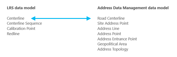
The following are required feature classes for the ArcGIS Linear Referencing schema to integrate with the Address Data Management solution:
Centerline
Centerline Sequence
Calibration Point
Redline
The following are required Address Data Management solution feature classes to integrate with ArcGIS Linear Referencing:
Road Centerline
Site Address Point
Address Line
Address Point
Address Entrance Point
Geopolitical Area
Address Topology
Tip:
You can run the Create LRS in Address Data Management solution tool to create an LRS in an Address Data Management geodatabase that contains an existing Road Centerline feature class.
The centerline feature class must include the following fields to successfully configure with an LRS and to take advantage of ArcGIS Linear Referencing and the Address Data Management solution configured together:
| Field | Data type | Length | IsNullable | Description |
|---|---|---|---|---|
| From Left | Short or Long | N/A | Yes | The first address on the left side of a roadway |
| To Left | Short or Long | N/A | Yes | The last address on the left side of a roadway |
| From Right | Short or Long | N/A | Yes | The first address on the right side of a roadway |
| To Right | Short or Long | N/A | Yes | The last address on the right side of a roadway |
| Full Name | Text | N/A | Yes | The name of the roadway |
The Site Address Point feature class must include the following fields to successfully configure with an LRS and to take advantage of ArcGIS Linear Referencing and the Address Data Management solution configured together:
| Field | Data type | Length | IsNullable | Description |
|---|---|---|---|---|
| Address Number | Short, Long, or Text | N/A | Yes | The site address number |
| Full Name | Text | N/A | Yes | The name of the roadway |
Custom address data model
To create a custom data model other than the Address Data Management solution, ensure that you include the required feature classes and tables for an LRS. This includes the centerline or line event feature class, and the Site Address Point feature class.
The following are required feature classes for the ArcGIS Linear Referencing schema to integrate with a custom address data model:
Centerline or line event
Centerline Sequence
Calibration Point
Redline
You must include a Site Address Point feature class to integrate with ArcGIS Linear Referencing.
The centerline or line event feature class must include the following fields to configure with an LRS using a custom address data model:
| Field | Data type | Length | IsNullable | Description |
|---|---|---|---|---|
| From Left | Short or Long | N/A | Yes | The first address on the left side of a roadway |
| To Left | Short or Long | N/A | Yes | The last address on the left side of a roadway |
| From Right | Short or Long | N/A | Yes | The first address on the right side of a roadway |
| To Right | Short or Long | N/A | Yes | The last address on the right side of a roadway |
| Road Name | Text | N/A | Yes | The name of the roadway |
The Site Address Point feature class must include the following fields to successfully configure with an LRS and to take advantage of ArcGIS Linear Referencing and a custom address data model:
| Field | Data type | Length | IsNullable | Description |
|---|---|---|---|---|
| Address Number | Short, Long, or Text | N/A | Yes | The site address number |
| Road Name | Text | N/A | Yes | The name of the roadway |
Note:
When using a custom address data model configured with an LRS, the additional capabilities of the Address Data Management solution are not included, such as specialized attribute rules, relationship classes, topology, special workflows, and more. You can re-create these capabilities in a custom address data model, but they are not available out of the box as they are with the Address Data Management solution.
Configure, load data, and publish an LRS with the Address Data Management solution in an ArcGIS Pro project
Both the Address Data Management solution and ArcGIS Linear Referencing have specific requirements to deploy in a geodatabase.
To configure, load data, and publish an LRS with the Address Data Management solution in an ArcGIS Pro project, complete the following steps:
Deploy the Address Data Management solution to your Enterprise portal.
Download and open the Address Data Management ArcGIS Pro project.
Create a calibration point feature class and a redline feature class that reside in the Address feature dataset in the Address Data Management geodatabase.
Note:
The field data type and length in the feature classes must adhere to the LRS data model.
Create a centerline sequence table that resides in the Address Data Management geodatabase.
Note:
The field data type and length in the table must adhere to the LRS data model.
Run the Create LRS From Existing Dataset tool with the Road Centerline, calibration point, redline, and centerline sequence layers as inputs.
Learn more about creating an LRS from an existing dataset
Note:
Ensure that the correct spatial reference; x,y,z and m-tolerance; and x,y,z and m-resolution are configured for feature classes used by ArcGIS Linear Referencing and Utility Network so that the LRS can be configured correctly.
Learn more about tolerance and resolution settings in the LRS
Run the Configure Address Feature Classes tool to associate the Road Centerline and Site Address Point feature classes as part of the Address Data Management solution and the LRS.
Use the Road Centerline feature class as the input for the Input Address Range Feature Layer parameter.
Load data into the Road Centerline and Site Address Point feature classes using the Append tool.
Note:
You can perform this step at any point between steps 3 and 7.
Create LRS Networks using one of the following tools:
Create LRS events using one of the following tools:
Load data into the LRS Network using the Append Routes tool.
Note:
The Append Routes tool considers existing centerlines when you check the Consider existing centerlines parameter. If a centerline ID value already exists where you append a route, the tool updates the existing centerline sequence record with the appended route's route ID value.
Load data into the LRS events using the Append Events tool.
Publish an LRS as a feature service.
Note:
When publishing an LRS as a feature service, the enterprise geodatabase connection file must use branch versioning. You must register the Address feature dataset and other required feature classes and tables as branch versioned before publishing.
Edit a feature service with LRS and address data in ArcGIS Pro
To edit a feature service that contains LRS and address data, complete the following steps:
Create and update any centerlines intended for use in LRS editing activities:
Provide attribute values in the
FromLeft,ToLeft,FromRight,ToRight, andRoadNamefields.Complete the LRS editing activity.
Run the Apply Event Behaviors tool to update the associated LRS data.
Validate the address topology to ensure all edits are valid.
To create or edit LRS events, use the event editing tools on the Linear Referencing tab in ArcGIS Pro or the Linear Referencing widgets in ArcGIS Experience Builder.
Combined LRS and address data editing
Combining an LRS and the Address Data Management solution in a feature service allows you to edit data managed by both with ArcGIS Pro. When editing a feature service with both LRS and address data from a single geodatabase, some LRS editing workflows may differ as described in the following sections.
Centerline split using a split tool
If the Road Centerline feature class from the Address Data Management solution is used as the LRS centerline feature class, an attribute rule exists within the layer to update the FromLeft, ToLeft, FromRight, and ToRight attribute values upon splitting a road centerline. This attribute rule proportionally updates the address values based on the split location.
The following image and table show a centerline before being split using the Split Centerline By Point tool:

| OID | From Left | To Left | From Right | To Right |
|---|---|---|---|---|
| 1 | 1120 | 1134 | 1117 | 1131 |
Splitting the centerline updates the FromLeft, ToLeft, FromRight, and ToRight attribute values.
The following image and table show the centerline and its attributes after the split operation:

| OID | From Left | To Left | From Right | To Right |
|---|---|---|---|---|
| 1 | 1120 | 1128 | 1117 | 1125 |
| 2 | 1130 | 1134 | 1127 | 1131 |
Centerlines split by an LRS edit
The following image and table show a centerline and the route attributes before route retirement:

| OID | Route ID | From Left | To Left | From Right | To Right |
|---|---|---|---|---|---|
| 1 | Route1 | 1120 | 1134 | 1117 | 1131 |
The route is retired from the start of the route to the middle portion of the route. As a result, the centerline is split, and its FromLeft, ToLeft, FromRight, and ToRight attribute values are updated.
The following table and image show the centerline and its attributes after route retirement:

| OID | Route ID | From Left | To Left | From Right | To Right |
|---|---|---|---|---|---|
| 1 | Route1 | 1120 | 1128 | 1117 | 1125 |
| 2 | Route1 | 1130 | 1134 | 1127 | 1131 |
Centerline merge using the Merge Centerlines tool
When using the Merge Centerlines tool  to merge centerlines that are associated with the same route, the
RoadName attributes must be identical across individual centerlines. The tool preserves the FromLeft and FromRight attribute values from the first (upstream) centerline and the ToLeft and ToRight attribute values from the last (downstream) centerline.
The following image and table show two centerlines before being merged:
| OID | From Left | To Left | From Right | To Right | Road Name |
|---|---|---|---|---|---|
| 1 | 1000 | 1010 | 2001 | 2011 | S. Main St. |
| 2 | 1012 | 1020 | 2013 | 2021 | S. Main St. |
Merging the centerlines updates the FromLeft, ToLeft, FromRight, and ToRight attribute values.
The following image and table show the merged centerline:
| OID | From Left | To Left | From Right | To Right | Road Name |
|---|---|---|---|---|---|
| 1 | 1000 | 1020 | 2001 | 2021 | S. Main St. |
Analysis capabilities in a combined LRS and Address Data Management dataset
Configuring an LRS and the Address Data Management solution in a single geodatabase also lets you combine the analysis capabilities of both data models on a roadway system. You can maintain, update, and improve your authoritative address repository while also maintaining, updating, and improving your authoritative roadway data.
Advanced Overlay Events capabilities
The Address Block Split Type parameter is available in the Overlay Events tool when you specify a configured Address Range layer as an input to the tool's Event Layers parameter.
The Address Block Split Type parameter specifies how the tool updates input address range values as part of the dynamic segmentation process. The Proportional option updates address range values proportionally for each segment from the split location, and the Nearest Address Point option updates address range values for each segment based on the nearest upstream and downstream address points.
Overlay Events scenarios
In the following diagram, a centerline feature, a Speed Limit line event, and a Sign point event are associated with a single route, S. Main St. The centerline layer is configured as the Address Range layer.

The route is calibrated from left to right between measures 0 and 10. The centerline, Speed Limit, and Sign layers are present on the route and have the input and output properties described in the subsections below.
Input layers
The following tables show the input layers' attributes:
Centerline
| Centerline ID | From Left | To Left | From Right | To Right | Road Name |
|---|---|---|---|---|---|
| RD-100 | 1000 | 1100 | 1001 | 1099 | S. Main St. |
Speed Limit
| Event ID | Route ID | From Measure | To Measure | From Date | To Date | Speed Limit |
|---|---|---|---|---|---|---|
| Speed1 | S. Main St. | 0 | 4 | 1/1/2000 | <Null> | 45 |
| Speed2 | S. Main St. | 4 | 10 | 1/1/2000 | <Null> | 35 |
Sign
| Event ID | Route ID | Measure | From Date | To Date | Sign Type |
|---|---|---|---|---|---|
| Sign1 | S. Main St. | 7 | 1/1/2000 | <Null> | Stop |
Output of proportional address block split type
When you choose the Proportional option for the Address Block Split Type parameter, the tool updates the address range values for each segment proportionally.
Moving in the direction of calibration of the route (from left to right):
The first segment is caused by the Speed Limit event, 45, which starts at measure 0 and ends at measure 4.
The second segment is caused by the Speed Limit event, 35, which starts at measure 4 and ends at measure 7 due to the presence of the Sign event, Stop.
The third segment is caused by the Sign event, Stop, at measure 7.
The final segment between measures 7 and 10 is caused by the Speed Limit event, 35.
The following diagram shows the output dataset when the Proportional option is chosen:

The following table provides details about the output dataset when the Proportional option is chosen:
| Route ID | Type | From Measure | To Measure | From Date | To Date | From Left | To Left | From Right | To Right | Road Name | Speed Limit | Sign Type |
|---|---|---|---|---|---|---|---|---|---|---|---|---|
| S. Main St. | Line | 0 | 4 | 1/1/2000 | <Null> | 1000 | 1040 | 1001 | 1039 | S. Main St. | 45 | <Null> |
| S. Main St. | Line | 4 | 7 | 1/1/2000 | <Null> | 1042 | 1070 | 1041 | 1069 | S. Main St. | 35 | <Null> |
| S. Main St. | Point | 7 | 7 | 1/1/2000 | <Null> | <Null> | <Null> | <Null> | <Null> | S. Main St. | 35 | Stop |
| S. Main St. | Line | 7 | 10 | 1/1/2000 | <Null> | 1072 | 1100 | 1071 | 1099 | S. Main St. | 35 | <Null> |
Output of nearest address point address block split type
When you choose the Nearest Address Point option for the Address Block Split Type parameter, the tool updates the address range values for each section based on the nearest upstream and downstream site address points.
Moving in the direction of calibration of the route (from left to right):
The first segment is caused by the Speed Limit event, 45, which starts at measure 0 and ends at measure 4.
The second segment is caused by the Speed Limit event, 35, which starts at measure 4 and ends at measure 7 due to the presence of the Sign event, Stop.
The third segment is caused by the Sign event, Stop, at measure 7.
The final segment between measures 7 and 10 is caused by the Speed Limit event, 35.
The following diagram shows the output dataset when the Nearest Address Point option is chosen:
The following table provides details about the output dataset when the Nearest Address Point option is chosen:
| Route ID | Type | From Measure | To Measure | From Date | To Date | From Left | To Left | From Right | To Right | Road Name | Speed Limit | Sign Type |
|---|---|---|---|---|---|---|---|---|---|---|---|---|
| S. Main St. | Line | 0 | 4 | 1/1/2000 | <Null> | 1000 | 1052 | 1001 | 1051 | S. Main St. | 45 | <Null> |
| S. Main St. | Line | 4 | 7 | 1/1/2000 | <Null> | 1054 | 1087 | 1053 | 1088 | S. Main St. | 35 | <Null> |
| S. Main St. | Point | 7 | 7 | 1/1/2000 | <Null> | <Null> | <Null> | <Null> | <Null> | S. Main St. | 35 | Stop |
| S. Main St. | Line | 7 | 10 | 1/1/2000 | <Null> | 1090 | 1100 | 1089 | 1099 | S. Main St. | 35 | <Null> |
This topic applies only to the surface transportation industry.