Extend routes
 Available with the Linear Referencing license.
Use the Extend Route tool to add length to the beginning or end of a route. As with other route editing activities, centerline features provide the location and geometry to extend a route. You can use existing centerline features in the centerline feature class, digitize them from aerial photography or basemaps, copy them from other feature classes, or import them from CAD files or other ArcGIS-supported data sources. In addition to extending a route, the Extend Route tool can update calibration points.
Before using this tool to edit a feature service, you must share branch versioned LRS data as a web layer. If the feature service is not yet published, see Share as web layers. If you are using a file geodatabase LRS dataset, this tool provides limited functionality.
Route extension follows gap calibration rules.
Beta:
You can use the ArcGIS Pro Assistant (Beta) to perform route extension and to guide you through the workflow.
Extend a route
To extend a route, complete the following steps:
Start ArcGIS Pro and add the centerline and LRS Network feature classes to a map.
You can also open a map in which the centerline and LRS Network layers are present.
Note:
In the LRS data model, only one centerline feature is expected at any given location. Ensure that the centerlines used for your edit do not overlap other centerlines in the LRS.
Branch versioned LRS Networks, including any network configured with a user-generated route ID, must be edited through a feature service.
Zoom to the location where you want to extend a route.
The centerline features for the route must exist before extending the route.
On the Linear Referencing tab, in the Route Editing group, click Extend
 .
The Extend Route pane appears with the Select By Rectangle tool
 as the default.
Select one or more centerlines on the map at the location of the route you want to extend.
Tip:
You can also click the Select one or more centerlines drop-down arrow and choose a different selection tool or use the interactive selection tools on the Map tab.
You can keep the centerlines selected after route edits by checking the Keep centerlines chosen and selected check box in the Linear Referencing options.
The selected centerlines are highlighted on the map, and the Allow choosing of one or more centerlines button
 appears in the Extend Route pane.
In the Extend Route pane, click Allow choosing of one or more centerlines
.The Chosen Centerlines section appears in the pane with the centerlines listed in order of selection. On the map, the selected centerlines are numbered and highlighted.
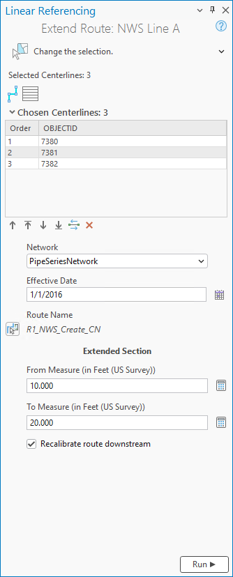
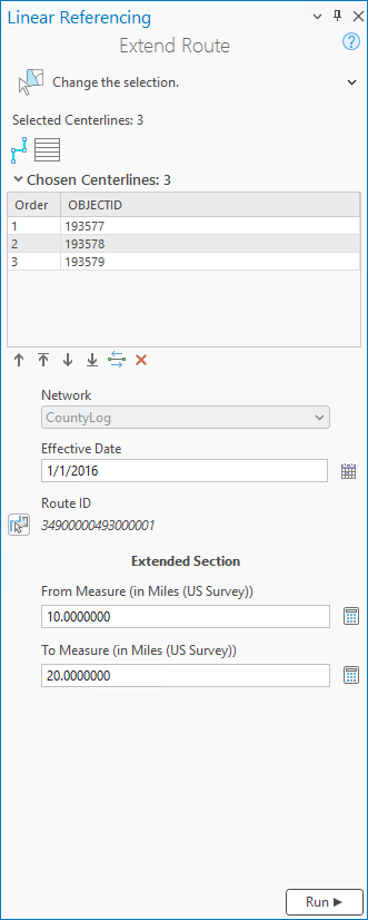
Note:
The direction of digitization determines the direction of calibration, increasing in the direction of digitization. You can reverse direction for the selected centerlines using the Flip the direction of the centerlines button
 . The flip occurs in memory only and is not permanent.
If the centerline contains curves, they are converted into a densified polyline feature.
Optionally, select one or more rows from the Order column and use the tools below the table to change the centerline selection order.
Tip:
You can also drag a row to change the order.
To change the display field in the Chosen Centerlines section, right-click the centerline feature class in the Contents pane, and choose Properties from the context menu. On the Layer Properties dialog box, click the Display tab, and click the Display field drop-down arrow to change its value. In the example above, the display field is
OBJECTID.
The following table describes the tools available in the Chosen Centerlines section:
Tool Tool name Tool description Allow choosing of one or more centerlines Allows you to choose the centerlines on the map and displays them in a table by order of selection. Use the move buttons below the table or drag rows to reorder the chosen centerlines. 
Clear the currently chosen centerlines Clears the chosen centerlines and keeps the selected centerlines. You can reselect after clicking this button or click the Allow choosing of one or more centerlines button a second time.
Move chosen centerlines up Moves one or more selected centerlines up a row in the table order. 
Move chosen centerlines to the top Moves one or more centerlines to the top of the table order. 
Move chosen centerlines down Moves one or more centerlines down a row in the table order. 
Move chosen centerlines to the bottom Moves one or more centerlines to the bottom of the table order. Flip the direction of the centerlines Reverses the direction of the chosen centerlines. The flip occurs in memory only and is not permanent. 
Remove the chosen centerlines Removes the chosen centerline from the table order but leaves it selected. The map reflects changes in the centerline selection order.
Click the Network drop-down arrow and choose the LRS Network to which you want to extend a route.
Click the Calendar
 next to the Effective Date text box and choose a start date for the route.
You can also double-click the Effective Date text box to insert the current date or enter a date in the box.
Click Choose route from map
 to select a route you want to extend on the map.
If multiple routes exist at the edit location, select one of the routes in the Select a Route dialog box.
If the centerlines do not touch the route at the extended location, the Extension Location parameter appears in the Extended Section section.
Tip:
After clicking Choose route from map
, you can hover over the routes to see the route and measure at the location of the pointer. You can set map scale options for display of route and measure information in the Linear Referencing options.When hovering near a feature, you can turn snapping on to improve the accuracy of the pointer.
Note:
You cannot extend a route to fill a gap between routes.
If the centerlines do not touch the route at the extended location, click the Extension Location drop-down arrow and choose Begin or End.
Verify that the automatically populated From Measure value appears as expected in the Extended Section section.
If the route is being extended at the end, the suggested From Measure value is the same as the To Measure value of the original route.
If the route is being extended at the beginning, the suggested From Measure value is 0.
Optionally, provide a start measure of your choice in the From Measure text box.
If you do not know the start measure, click Recalculate From Measure
 to calculate a suggested start measure. This value is calculated as the difference between the To Measure value and the geometric length of the centerline.
Note:
Z-values are considered when calculating the geometric length of the centerlines.
For an engineering (line) network, you can provide measures as station values in the 00+00.00 or 00+00.000 format.
Verify that the automatically populated To Measure value appears as expected in the Extended Section section.
If the route is being extended at the end, the suggested To Measure value is the suggested From Measure value plus the geometric length of the centerline.
If the route is being extended at the beginning, the suggested To Measure value is the suggested From Measure value plus the geometric length of the centerline.
Optionally, provide an end measure of your choice in the To Measure text box.
If you do not know the end measure, click Recalculate To Measure
to calculate a suggested start measure. This value is calculated as the sum of the From Measure value and the geometric length of the centerline.Optionally, if the route is being extended at the beginning, keep the Recalibrate route downstream check box checked to update the measures downstream of the extension.
Click Run.
The route is extended. The original route is retired with its end date field populated with the Effective Date value. A newly extended route is created with its start date field populated with the Effective Date value, and the end date field populated with a null value.
Note:
If the route edit introduces one or more physical gaps on the route, a prompt appears before the tool runs. If you don't plan to create a gapped route, click No. You can disable this warning by unchecking the Warn before allowing route edits that can create physical gaps check box in the Linear Referencing options.
If the route already has one or more physical gaps and the edit does not introduce more, no prompt appears.
If a message about acquiring locks appears, it means that conflict prevention is enabled. After you select a route, the tool attempts to release the route lock if the active user acquires the route lock in a different named version and the releasable status value is Yes.
Route extension scenarios when there is an equation point
The following sections describe a few route extension scenarios when there is an equation point.
For an engineering (line) network, if the start or end measures of the extended section of the route results in an equation point, the route is not extended. Routes must be created using the Create Route tool.
Route extension at the beginning of a route
In this example, Route X has measures from 0 feet to 10 feet. The geometric length of the centerline used for extension is 10 feet. When you extend the route at the beginning, the measures for the extended section start at 0 feet and end at 10 feet.
The following diagram shows the centerline and Route X before route extension:

If the Recalibrate route downstream check box is checked, the original part of the route is recalibrated, and the resulting extended route has measures from 0 feet to 20 feet:

If the Recalibrate route downstream check box is not checked, the measures for the extended section that start at 0 feet and end at 10 feet result in an equation point, and the route is not extended. Routes must be created using the Create Route tool.
Route extension at the end of a route
In this example, Route X has measures that go from 0 feet to 10 feet. The geometric length of the centerline used for extension is 10 feet:

When you extend the route from the end, if you set the measures for the extended section to start at 5 feet and end at 15 feet, this results in an equation point where the centerline and the original route meet. At this equation point, the back station is 10 feet and the ahead station is 5 feet. In this case, the route is not extended. Routes must be created using the Create Route tool.
Example of downstream recalibration for nonline networks
For a nonline network, the Extend Route tool always recalibrates route measures downstream from the extended section.
In this example, Route X has measures from 0 feet to 10 feet before route extension. The geometric length of the centerline used for extension is 10 feet. When you extend this route from the beginning, the measures for the extended section start at 0 feet and end at 10 feet.
The following diagram shows the centerline and Route X before route extension:
When the measures are recalibrated downstream, the original part of the route is recalibrated and the resulting extended route has measures from 0 feet to 20 feet:
Route extension in a utility network dataset
After configuring a utility network for use with an LRS using the Configure Utility Network Feature Classes tool, you can extend routes using the steps above.
In a combined LRS and utility network dataset, the centerline features in the centerline (Pipeline Line) feature class involved in route extension can have prepopulated start and end measures.
Note:
If the measures are not provided using the centerline feature class, the LRS route editing tools provide start and end measures on the route.
When you use multiple centerlines, the coincident points of the centerline features must have the same measures. The tool populates the start and end measures of the route using these measure values.
Coincident points of the centerline match
In the following example, the end measure of CL1 (14) matches the start measure of CL2 (14):

Route X can be extended at the beginning using centerlines CL1 and CL2 because their start and end measures match. Calibration points are created at the end of each centerline when Route X is extended.
Coincident points of the centerline do not match
In the following example, the end measure of CL2 (25) does not match the start measure of CL3 (19):

Route X cannot be extended at the beginning using centerlines CL1 and CL2 because the start and end measures of CL2 and CL3 do not match.
Nonmonotonic route due to centerline selection order
In the following example, Route X cannot be extended at the beginning using centerlines CL1 and CL2. Even though the coincident points of the centerlines match, the order of their selection (CL2 followed by CL1) causes the extended portion of Route X to be nonmonotonic.

Nonmonotonic route
In the following example, Route X cannot be extended at the beginning using centerlines CL1 and CL2. Even though the coincident points of the centerlines match, the start and end measures of CL2 are the same (19) and cause the extended portion of Route X to be nonmonotonic.

Opposite centerline directions
In the following example, Route X cannot be extended at the beginning using centerlines CL1 and CL2. Even though the coincident points of the centerlines match, the direction of CL2 is the opposite direction to that of the route.

Route extension in a line network
The following examples show route extension in a line network.
Route extension at the beginning of a line
In this example, Route X has a start measure of 15 and an end measure of 20. Route X is extended from the beginning. The proposed start measure of the extended section is 5 and the proposed end measure is 10.
The following diagram shows the centerline and routes before route extension:

If you choose not to recalibrate the route downstream, the Route X measures after extension are 5 and 10 for the first part and remain as 15 and 20 for the second part.
The line orders after the extension are recalculated. The line order for the extended part of Route X is 100 and Route Y is 200:

Route extension at the end of a line
In this example, Route X is extended at the end of a line. Route X has existing measures from 5 to 10. The proposed start and end measures are 15 to 20.
The following diagram shows the centerline and routes before route extension:

The Route X measures after extension are 5 and 10 for the first part, and 15 and 20 for the second part.
In this example, there is no change in the line order because the route is extended at the end:
