Mesh symbols
Mesh symbols draw the features in multipatch layers and 3D object scene layers. These layers must be in the 3D Layers category of a scene to use mesh symbols.
Material and Procedural fill types
When a mesh symbol is applied to multipatch features, the fill symbol layer can be of type Material fill or Procedural fill. When a mesh symbol is applied to 3D object scene layer features, the fill symbol layer type must be material fill.
Material fill type
Symbol layers set to material fill type include a material mode to specify how the selected color is applied, as explained in the following table.
| Material mode type | Description |
|---|---|
| Multiply | The RGB values of the object are multiplied by the RGB values of the selected color. This is generally the best choice when the object is white or nearly white. |
| Tint | The hue and saturation components of the selected color replace those of the object. The value components of the selected color and the object color are multiplied to obtain the final value component. This is generally the best choice when you want to overlay color to an already colored object. |
| Replace | The texture and color of the object are fully replaced by the selected color. |
Procedural fill type
Procedural fill symbol layers rely on a rule package to define the symbol properties. The rule package associated to a procedural fill symbol layer in a mesh symbol must have the @StartRule coded value specify @InMesh annotation, so it can be applied to multipatch geometry.
Mesh symbol structure
Mesh symbols contain a fill symbol layer and a stroke symbol layer. The fill symbol layer draws the surfaces of the mesh features and a stroke symbol layer can draw outlines on the edges of the features. You cannot add additional fill or stroke symbol layers. When the fill type is procedural fill edge outlines cannot be drawn and no stroke symbol layer is included in the mesh symbol.
When fill type is Material fill, mesh symbols have three basic properties, Color, Outline Color, and Outline Width. These are defined in the Format Symbol mode of the Symbology pane, on the Properties tab, on the Symbol tab ![]() , under the Appearance group. Color applies to the fill symbol layer and applies only when the symbol layer is color unlocked.. Outline Color and Outline Width are applied to the stroke symbol layer.
, under the Appearance group. Color applies to the fill symbol layer and applies only when the symbol layer is color unlocked.. Outline Color and Outline Width are applied to the stroke symbol layer.
Mesh symbol edge outlines
The edges of material fill mesh symbols can be visually enhanced by a stroke symbol layer in the mesh symbol. To add edges to a mesh symbol, choose an Outline Color and set the Outline Width.
In the Format Symbol mode of the Symbology pane, on the Properties tab, on the Layers tab ![]() , under the Appearance group, select the stroke symbol layer to change the color and width of the edge outlines. Stroke symbol layers in a mesh symbol are of type Solid stroke only. From here you can also set the threshold angle properties.
, under the Appearance group, select the stroke symbol layer to change the color and width of the edge outlines. Stroke symbol layers in a mesh symbol are of type Solid stroke only. From here you can also set the threshold angle properties.
Unlike stroke symbol layers in other symbols, there are no additional properties you can set. The profile of the stroke is always square, with the anchor set to center, the caps set to square, and the joins set to round.
Threshold angle properties
Every 3D object consists of multiple faces, including a back and front side. The Threshold angle is the minimum angle between the face normals at which the stroke is drawn, and the default value is 35 degrees. By enabling the Apply threshold angle to both sides of faces option, the stroke is applied to both sides of the face.
When this option is checked, the default threshold angle is supplementary to 180 degrees. For example, you can specify a value of 35 degrees or 145 degrees, and the stroke is drawn at the same face because the threshold angle applies to both faces. If a 3D object feature has an acute angle, you can set the threshold higher. To see the stroke on edges with an obtuse angle, set the value lower than the default to ensure an edge is drawn. The threshold angle supports attribute-driven symbology to set the value based on an attribute.
| Low threshold angle example | Default threshold angle example |
|---|---|
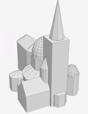 |
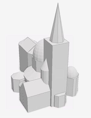 |
| The edges of the domes are outlined with a low threshold angle of 5 degrees. | The edges of the domes are not outlined with the default threshold angle of 35 degrees. |
Mesh symbol layers in 2D
If you move a layer symbolized with mesh symbols into the 2D Layers category of a scene or copy it into a map, the features are redrawn with polygon symbols. Conversely, if you drag a multipatch layer from the 2D Layers category to the 3D Layers category of a scene, the features draw with a mesh symbol.
When you move a mesh symbol with a procedural fill symbol layer into a 2D context, the procedural rule package is no longer valid because it references a rule package where the @StartRule coded value specifies @InMesh annotation. Choose a rule package with a @StartRule coded value that specifies @InPoly instead. Rule packages are created in ArcGIS CityEngine.