Create TIN (3D Analyst Tools)
Summary
Creates a triangulated irregular network (TIN) dataset.
Illustration
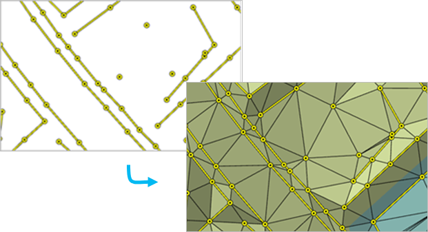
Usage
Avoid creating a TIN using a geographic coordinate system, as the Delaunay triangulation rule cannot be effectively enforced when the x,y units are expressed in spherical coordinates.
The surface feature type defines how the input features will contribute to the definition of the triangulated surface.
Point features can be specified as mass points, which provide data nodes with z-values that are used in the triangulation of the surface.
Line features can be specified as mass points and breaklines, which represent locations along a surface with linear discontinuities in slope, such as ridge lines, shore lines, pavement edges, building footprints, and so on.
Polygon features can also be specified as mass points and breaklines, along with clip features that define the data area, replace features that define regions with constant z-values (for example, water bodies), and erase features that indicate interior areas where data does not exist.
The tool can create a TIN composed of many millions of points given enough memory. However, limiting the number of TIN nodes to less than 6 million will ensure a responsive display performance and overall usability. If a larger TIN surface is needed, consider using a terrain dataset. The terrain dataset offers a multiresolution TIN surface that can support much larger collections of source measurements.
Set the Default TIN Storage Version environment to
PRE_10.0if the TIN being created will be used in versions of ArcGIS Desktop earlier than 10.0.Once a TIN dataset is created, you can modify it using the Edit TIN tool to incorporate additional feature-based measurements into the TIN surface. You can also use the Delineate TIN Data Area tool to define which TIN triangles constitute the interpolation zone based on the maximum length of a triangle edge. The TIN surface can also be modified through interactive editing.
Parameters
| Label | Explanation | Data type |
|---|---|---|
|
Output TIN |
The TIN dataset that will be generated. |
TIN |
|
Coordinate System (Optional) |
The spatial reference of the output TIN. Set the spatial reference to a projected coordinate system. Geographic coordinate systems are not recommended because Delaunay triangulation cannot be guaranteed when the x,y coordinates are expressed in angular units, which could have an adverse impact on the accuracy of distance-based calculations, such as slope, volume, and line of sight. |
Coordinate System |
|
Input Feature Class (Optional) |
The input features and their related properties that define how they will be added to the TIN. Value table columns:
|
Value Table |
|
Constrained Delaunay (Optional) |
Specifies the triangulation technique that will be used along the breaklines of the TIN.
|
Boolean |
Environments
Current Workspace, Output Coordinate System, Extent, Geographic Transformations, Default TIN Storage Version
Licensing information
- Basic: Requires 3D Analyst
- Standard: Requires 3D Analyst
- Advanced: Requires 3D Analyst