Visibility (3D Analyst Tools)
Summary
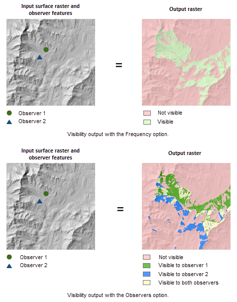
Determines the raster surface locations visible to a set of observer features, or identifies which observer points are visible from each raster surface location.
The Geodesic Viewshed tool provides enhanced functionality or performance.
Illustration
Usage
This tool supports two visibility analysis types, Frequency and Observers, which is controlled by the Analysis type tool parameter. For the first type, the tool determines which raster surface locations are visible to a set of observers. For the other, it identifies which observers are visible from each raster surface location.
If the input raster contains undesirable noise caused by sampling errors, and you have the ArcGIS Spatial Analyst extension, you can smooth the raster with a low-pass filter, such as the Mean option of the Focal Statistics tool, before running this tool.
The visibility of each cell center is determined by comparing the altitude angle to the cell center with the altitude angle to the local horizon. The local horizon is computed by considering the intervening terrain between the point of observation and the current cell center. If the point lies above the local horizon, it is considered visible.
An optional above-ground-level (AGL) output raster is provided by the tool. Each cell on the AGL output raster records the minimum height that needs to be added to that cell to make it visible by at least one observer.
When the input observer features contain multiple observers, the output value is the minimum of the AGL values from all of the individual observers.
Use the observer parameters to gain more control over the visibility analysis process. For example, through the observer offset parameter, you may specify an offset to the observer elevation in the visibility analysis.
When the input raster needs to be resampled, the bilinear technique will be used. An example of when an input raster may be resampled is when the output coordinate system, extent, or cell size is different from that of the input.
Parameters
| Label | Explanation | Data type |
|---|---|---|
|
Input raster |
The input surface raster. |
Raster Layer |
|
Input point or polyline observer features |
The feature class that identifies the observer locations. The input can be point or polyline features. |
Feature Layer |
|
Output raster |
The output raster. The output will either record the number of times that each cell location in the input surface raster can be seen by the input observation locations (the frequency analysis type), or record which observer locations are visible from each cell in the raster surface (the observers type option). |
Raster Dataset |
|
Output above ground level raster (Optional) |
The output above-ground-level (AGL) raster. The AGL result is a raster where each cell value is the minimum height that must be added to an otherwise nonvisible cell to make it visible by at least one observer. Cells that were already visible will have a value of 0 in this output raster. |
Raster Dataset |
|
Analysis type (Optional) |
The visibility analysis type.
|
String |
|
Use NoData for non-visible cells (Optional) |
Value assigned to non-visible cells.
|
Boolean |
|
Z factor (Optional) |
Number of ground x,y units in one surface z unit. The z-factor adjusts the units of measure for the z units when they are different from the x,y units of the input surface. The z-values of the input surface are multiplied by the z-factor when calculating the final output surface. If the x,y units and z units are in the same units of measure, the z-factor is 1. This is the default. If the x,y units and z units are in different units of measure, the z-factor must be set to the appropriate factor, or the results will be incorrect. For example, if your z units are feet and your x,y units are meters, you would use a z-factor of 0.3048 to convert your z units from feet to meters (1 foot = 0.3048 meter). |
Double |
|
Use earth curvature corrections (Optional) |
Specifies whether correction for the earth's curvature will be applied.
|
Boolean |
|
Refractivity coefficient (Optional) |
The coefficient of the refraction of visible light in air. The default value is 0.13. |
Double |
|
Surface offset (Optional) |
A vertical distance that will be added to the z-value of each cell as it is considered for visibility. It must be a positive integer or floating-point value. You can select a field in the input observers dataset, or you can specify a numerical value. By default, a numerical field If no value is provided for this parameter and the default field does not exist in the input observer features attribute table, the default value is 0. |
Double; Field |
|
Observer elevation (Optional) |
The surface elevations of the observer points or vertices. You can select a field in the input observers dataset, or you can specify a numerical value. By default, a numerical field If this parameter is unspecified and the default field does not exist in the input observer features attribute table, it will be estimated through bilinear interpolation with the surface elevation values in the neighboring cells of the observer location. |
Double; Field |
|
Observer offset (Optional) |
A vertical distance that will be added to the observer elevation. It must be a positive integer or floating-point value. You can select a field in the input observers dataset, or you can specify a numerical value. By default, a numerical field If this parameter is unspecified and the default field does not exist in the input observer features attribute table, it defaults to 1. |
Double; Field |
|
Inner radius (Optional) |
The start distance from which visibility will be determined. Cells closer than this distance will not be visible in the output but can still block visibility of the cells between inner radius and outer radius. It can be a positive or negative integer or floating point value. If it is a positive value, then it is interpreted as three-dimensional, line-of-sight distance. If it is a negative value, then it is interpreted as two-dimensional planimetric distance. You can select a field in the input observers dataset, or you can specify a numerical value. By default, a numerical field If no value is provided for this parameter and the default field does not exist in the input observer features attribute table, the default value is 0. |
Double; Field |
|
Outer radius (Optional) |
The maximum distance from which visibility will be determined. Cells beyond this distance will be excluded from the analysis. It can be a positive or negative integer or floating point value. If it is a positive value, then it is interpreted as three-dimensional, line-of-sight distance. If it is a negative value, then it is interpreted as two-dimensional planimetric distance. You can select a field in the input observers dataset, or you can specify a numerical value. By default, a numerical field If this parameter is unspecified and the default field does not exist in the input observer features attribute table, it defaults to infinity. |
Double; Field |
|
Horizontal start angle (Optional) |
The start angle of the horizontal scan range. Provide the value in degrees from 0 to 360 with 0 oriented to north. The value can be integer or floating point. The default value is 0. You can select a field in the input observers dataset, or you can specify a numerical value. By default, a numerical field If no value is provided for this parameter and the default field does not exist in the input observer features attribute table, the default value is 0. |
Double; Field |
|
Horizontal end angle (Optional) |
The end angle of the horizontal scan range. Provide the value in degrees from 0 to 360 with 0 oriented to north. The value can be integer or floating point. The default value is 360. You can select a field in the input observers dataset, or you can specify a numerical value. By default, a numerical field If this parameter is unspecified and the default field does not exist in the input observer features attribute table, it defaults to 360. |
Double; Field |
|
Vertical upper angle (Optional) |
The upper vertical angle limit of the scan relative to the horizontal plane. Provide the value in degrees from above -90 up to and including 90. The value can be integer or floating point. The default value is 90 (straight up). You can select a field in the input observers dataset, or you can specify a numerical value. By default, a numerical field If this parameter is unspecified and the default field does not exist in the input observer features attribute table, it defaults to 90. This parameter value must be greater than the Vertical lower angle parameter value. |
Double; Field |
|
Vertical lower angle (Optional) |
The lower vertical angle limit of the scan relative to the horizontal plane. Provide the value in degrees from -90 up to but not including 90. The value can be integer or floating point. The default value is -90 (straight down). You can select a field in the input observers dataset, or you can specify a numerical value. By default, a numerical field If this parameter is unspecified and the default field does not exist in the input observer features attribute table, it defaults to -90. This parameter value must be less than the Vertical upper angle parameter value. |
Double; Field |
Environments
Auto Commit, Cell Size, Cell Size Projection Method, Compression, Current Workspace, Extent, Geographic Transformations, Mask, Output CONFIG Keyword, Output Coordinate System, Scratch Workspace, Snap Raster, Tile Size
Licensing information
- Basic: Requires 3D Analyst or Spatial Analyst
- Standard: Requires 3D Analyst or Spatial Analyst
- Advanced: Requires 3D Analyst or Spatial Analyst