Network analysis layers
A network analysis layer is a special type of group layer used to perform an analysis using the ArcGIS Network Analyst extension in ArcGIS Pro. The layer references a specific network data source, has a set of analysis settings, and includes the inputs and outputs of the analysis. Each Network Analyst solver (for example, Service Area, Closest Facility, etc.) has an associated network analysis layer type with a specific schema and list of analysis settings.
Network analysis layer workflow
Network analysis layers are used for performing a network analysis workflow in ArcGIS Pro. The typical workflow follows these steps:
Create the network analysis layer referencing the desired network data source.
Configure the desired analysis settings.
Load input data into the network analysis layer's sublayers.
Solve the analysis.
View and work with the analysis results.
This section explains, in general terms, how to perform each of these steps. For more detail, refer to the Network Analyst solver tutorials.
Create a network analysis layer
A network analysis layer can be created using a UI workflow in ArcGIS Pro or using geoprocessing tools in the Network Analyst Tools toolbox (for example, Make Closest Facility Analysis Layer). Learn more about how to create a network analysis layer
Configure analysis settings
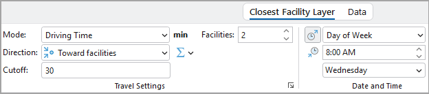
The network analysis layer includes settings that can be used to configure the analysis to your needs.
Frequently used settings can be viewed and adjusted using the network analysis layer's contextual ribbon.
Other, more advanced settings can be viewed and adjusted using the network analysis layer's property pages, which can be accessed by right-clicking the layer in the Contents pane and choosing Properties or using one of the launch buttons on the contextual ribbon ![]() .
.
Load input data
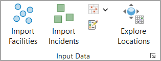
Input data for the analysis must be loaded into the input sublayers of the network analysis layer. Effectively, the data must be copied into the sublayer and transformed to match the sublayer's schema.
Input data can be added to the sublayers using the Import buttons on the Input Data group in the layer's contextual ribbon or using the Add Locations geoprocessing tool.
Solve the analysis
Solving the network analysis layer performs the network analysis calculation and generates results. Solve the analysis by clicking the Run button on the network analysis layer's contextual ribbon or using the Solve geoprocessing tool.

Work with the analysis results
When you solve the layer, the network analysis layer is updated to include the analysis results.
Work with analysis results in sublayers
Some sublayers of the network analysis layer are output-only sublayers which are populated when the solve completes. Some sublayers include both input and output fields, and the output fields are updated when the solve completes. The analysis results can be examined visually in the map and by viewing the attribute tables of these sublayers.
Sublayers can be used as inputs to other geoprocessing tools for further analysis. Use geoprocessing tools such as Export Features to export sublayer data into another feature class.
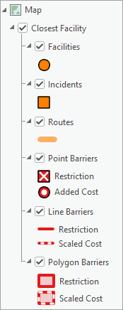
Adjust layer symbology
The symbology of a network analysis layer can be configured using the Symbology pane, which can be accessed using the Symbology button on the layer's contextual ribbon when the group layer is selected in the Contents pane. Multiple configuration options are available for controlling the symbology of all sublayers of the network analysis layer together in a coordinated fashion to help visualize the results of an analysis.
Learn more about network analysis layer symbology
The symbology of individual sublayers of a network analysis layer can also be adjusted separately like any other feature layer.
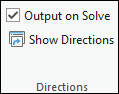
View turn-by-turn directions
Some Network Analyst solvers produce turn-by-turn directions as one of the analysis outputs. Directions can be viewed in the Directions pane by clicking the Show Directions button on the layer's contextual ribbon.
Share a network analysis layer
When sharing a network analysis layer, care must be taken to ensure that the layer remains connected to its network data source and analysis data. The best way to share a network analysis layer is to create a layer package (.lpkx).
The Package Layer geoprocessing tool can be used to package a network analysis layer and includes a parameter, Exclude Network Dataset, which allows you to choose whether to include the layer's network data source in the package. You can exclude the network data source if the person you're sharing the layer with has a copy of the same network or can access it on a shared file system. This saves disk space by not making a copy of the network. When the package is extracted, the layer may be broken, but it can be reconnected to the network dataset.
Copy a network analysis layer
For some workflows, it can be helpful to create multiple, similar network analysis layers and vary the analysis settings or input data and compare the results. An existing network analysis layer can be duplicated by right-clicking the layer in the Contents pane and choosing Duplicate or using the Copy Network Analysis Layer geoprocessing tool.
Learn more about how to copy a network analysis layer
Delete a network analysis layer
Network analysis layers are often used as part of a larger workflow. When the network analysis layer is no longer needed, it can be deleted by right-clicking the layer in the Contents pane and choosing Delete or using the Delete Network Analysis Layer geoprocessing tool.
Caution:
A network analysis layer can be removed from the map by right-clicking the layer in the Contents pane and choosing Remove. However, removing the layer does not delete the layer's source data, and it is not possible to reconstruct the layer from the source data. For this reason, if you no longer need the layer, you should delete it as described above instead of simply removing it from the map.
Components of a network analysis layer
Network analysis layers are group layers that contain the input and output data for an analysis, hold configurable analysis settings, and reference a network data source. This section describes each of these components in more detail.
Network data source
A network analysis layer references a specific network data source, which is the street network used to calculate travel times, distances, and optimal paths when solving the analysis. The network data source can be a network dataset on disk or a routing service.
Use the following steps to check which network data source a network analysis layer uses:
Right-click the network analysis layer in the Contents pane and choose Properties.
In the Properties dialog, click Source.
The network data source information is shown in the Data Source section.
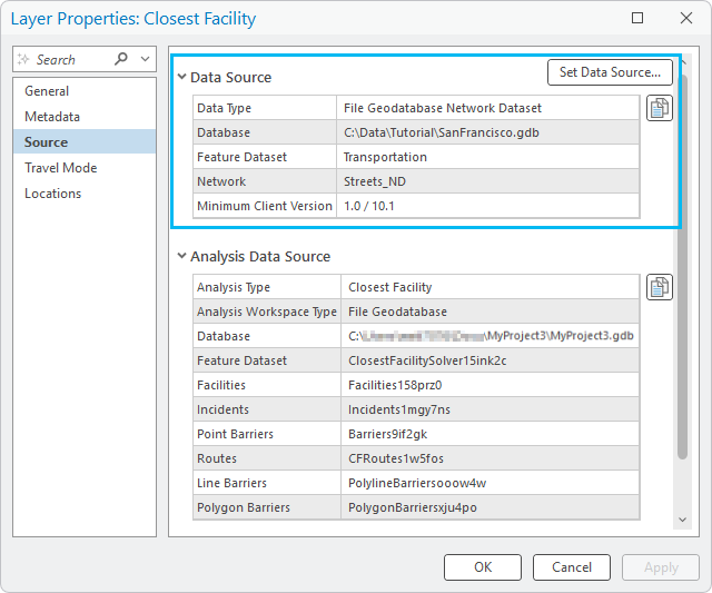
Although it is possible to change the network data source of a network analysis layer, this should only be done to reconnect the layer if the network dataset's file path has changed or if the new network's schema (sources, attributes, etc.) is exactly the same as the former one.
Analysis data source
The network analysis layer's input and output data are contained in the group layer's sublayers, which reference data stored on disk in file geodatabase feature classes and tables. The list of sublayers and their schemas depend on the network analysis layer's solver. Refer to the documentation for each solver to learn more about the sublayers and their schemas.
When creating a network analysis layer in a project, by default, the layer's data will be created in a new, automatically-named feature dataset in the Current Workspace geoprocessing environment, which is usually the project geodatabase. Table-based data will be created at the root level of the same geodatabase because tables cannot be stored in a feature dataset. You can override this behavior using the Analysis Geodatabase and Analysis Feature Dataset Name parameters in the geoprocessing tool used to create the layer (for example, Make Closest Facility Analysis Layer).
Use the following steps to see where a network analysis layer's analysis data is stored:
Right-click the network analysis layer in the Contents pane and choose Properties.
In the Properties dialog, click Source.
The network data source information is shown in the Analysis Data Source section.
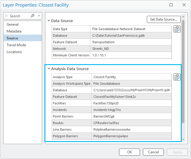
A network analysis layer's analysis data source cannot be changed once the layer has been created.
Note:
If the solver supports turn-by-turn directions, feature classes holding the directions data are also included in the same feature dataset as the sublayer data.
Contextual ribbon
Each network analysis layer has its own set of contextual ribbons. The solver layer ribbon (for example, the Closest Facility Layer ribbon) can be used to view and adjust analysis settings, load data into the analysis, solve the analysis, and view and visualize analysis results. Refer to the documentation for each solver to learn more about the contextual ribbon for that solver. The Data ribbon includes tools for working with the layer's network data source.
The network analysis layer's contextual ribbons are available when the layer or any of its sublayers is selected in the Contents pane.
The contextual ribbon is specific to the selected network analysis layer; it always displays the current settings of the selected layer and is used to work with that layer.