Work with Oriented Imagery Viewer
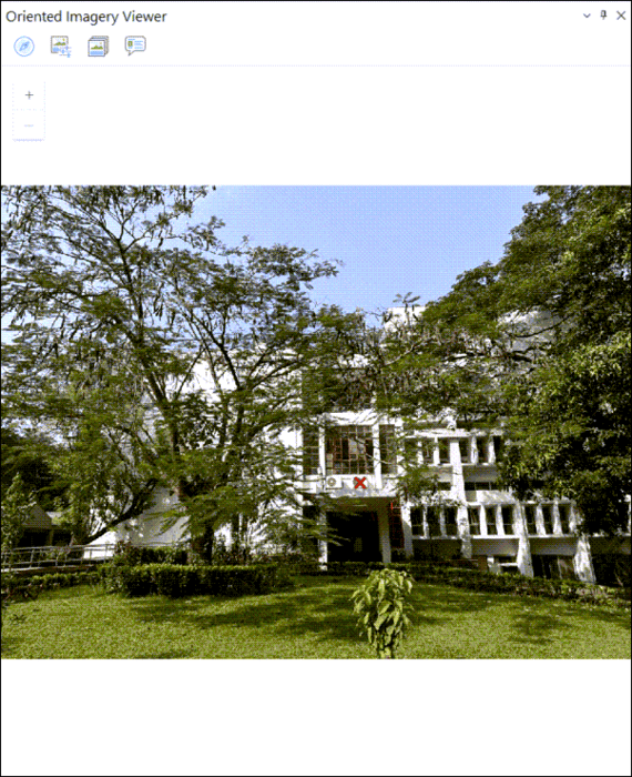
Oriented images are displayed in the Oriented Imagery Viewer. The viewer includes tools that support exploring and managing images in an oriented imagery layer. Click a point on a map or a scene, and view any image in the collection that depicts that point. You can view assets from multiple directions and enhance contrast, brightness, and sharpening to better view an image. As you pan and zoom in an image, the camera's field of view dynamically updates on the map, and can be related to any vector data in the map.
Explore images
The Explore Images tool allows you to view oriented imagery associated with any location in a map or scene. The tool provides multiple ways to search, filter, and view imagery. The Explore Images tool gives three options:
- Select 2D
 and click the map or scene. The best available image of the location is loaded (assuming the oriented imagery layer has coverage in that location). The red cross
  in the loaded image is seen at the best estimate for the selected location.
Select 3D
 and click a location in a scene. This option extends 2D explore capability by adding a height filter. This option is disabled in a map and supported only in a scene. The tool uses the
 Vertical Search Rangeproperty to filter 3D features by height, returning only those within the specified vertical range of the selected point. For more details onVertical Search Rangerefer to the parameters of Update Oriented Imagery Dataset Properties.Select Display Image
 to display only the image associated with the selected camera point. When selected, you can click an oriented imagery feature directly on the map and the associated image opens in the viewer. No filters are applied to identify the best image.
Note:
The best image choice for the location is based on the distance of the camera from the selected location, the camera heading (direction), and the camera pitch (obliquity). If a camera location is directly selected, the corresponding image is displayed. However, in most cases, it is recommended that you select the location of interest and allow the system to determine the best image.
Explore additional images in the Oriented Imagery Viewer
To explore additional images in the Oriented Imagery Viewer, do the following:
Select the Navigation tool
 to explore the images that contain the selected location on the map using a compass.
 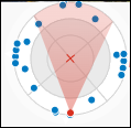 . The selected location is visualized as a red cross in the center of the Navigation tool and on the map. Camera location for images that include the selected map location are shown as points on the tool, arranged based on their distance and heading relative to the red cross . The tool is divided into four quadrants (north, south, east, and west); each quadrant is divided into three segments that show the relative distance of each camera location from the selected location on the map. Segments with images are shown in white; segments without images are gray. For the current image in the Oriented Imagery Viewer, the camera location and heading relative to the red cross are shown in red. Additional camera locations depicting the selected map location are shown in blue. To view a different image of the selected map location, click a blue dot, or click another segment (in white).
Select Image Gallery
 to explore a carousel of low-resolution thumbnails of all images that depict the selected map location. Click a thumbnail to view the full-resolution image in the Oriented Imagery Viewer.
Note:
The Image gallery carousel is supported only for image formats that are internally tiled, such as
.mrfor.cog. The Image gallery is not supported for JPEG images. If the image format is not supported by Image gallery, the tool is unavailable.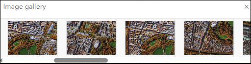
Enhance images
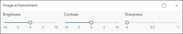
Select the Image enhancement tool ![]() to adjust brightness, contrast, and sharpness of the image in the Oriented Imagery Viewer using interactive sliders. New settings will be maintained for subsequent images loaded in the viewer. Use the Reset button
to adjust brightness, contrast, and sharpness of the image in the Oriented Imagery Viewer using interactive sliders. New settings will be maintained for subsequent images loaded in the viewer. Use the Reset button ![]() to reset to the original values at any time.
to reset to the original values at any time.
Note:
The Image enhancement tool is not available for 360-degree images.
View the pop-up
Click the Pop-up button ![]() to view the pop-up for the image in the Oriented Imagery Viewer. Refer to Configure pop-ups for details on configuring pop-ups for feature layers.
to view the pop-up for the image in the Oriented Imagery Viewer. Refer to Configure pop-ups for details on configuring pop-ups for feature layers.
Image overlays
You can visualize feature layers as overlays in the oriented imagery viewer. The following types of overlays are available:
Overlay Features—The Overlay Features tool consists of a toggle button
 that shows or hides the overlay of all the selected layers on the image. From the drop-down menu, select the feature layers from the Edit Layer list to overlay the features on the image.
Overlay Cameras—Click Overlay Cameras
 to overlay the camera locations from the oriented imagery layer that intersects the footprint of the loaded image.
Note:
The symbology and visibility settings of the features you overlay in the oriented imagery viewer correspond with those shown on the map. Any updates to the feature's symbology are reflected in the viewer upon refresh.
Visualization of point overlays are only supported on Frame Imagery.
Data capture
You can capture features inside the feature layer from the Oriented Imagery Viewer, however, the feature layer must have the following fields to enable data capturing:
A BLOB field to store the geometry of the captured feature in image space. This field name has to be assigned to the
Image Geometry Fieldproperty. Refer to the parameters detailed in Update Oriented Imagery Dataset Properties for more information.An integer or string field to store the unique reference ID of the image on which the feature was captured. This field name has to be assigned to the
Image Reference Fieldproperty. Refer to the parameters detailed in Update Oriented Imagery Dataset Properties for more information.
By default, the ObjectID of the Oriented Imagery Dataset is the unique reference ID. You can change this by assigning any other field containing unique IDs to the Reference ID Field. Refer to the parameters detailed in Update Oriented Imagery Dataset Properties for more information.
To start capturing the features, follow the steps below.
Click the Overlay Features drop-down menu, select a layer from the Layers list.
Click Data Capture
 , and select the editing tool point
  , line
  , or polygon
  from the list of available tools.
Digitize features on the image. Double click the feature to end digitizing.
Note:
Data Capture is enabled only for layers that successfully pass the schema check. If a layer does not pass the schema check, the icon will not be displayed. This indicates that such layers can be overlaid on the image only, but cannot be used for data capture.
Note:
For a point feature layer, users can capture an asset using line or polygon geometry, however, this shape will only be visible as an overlay on the image where it was originally captured. On other images and on the map, the asset will continue to be represented as a point.
Use the Measure In Image tool
The Measure In Image tool allows you to take geodesic measurements in the oriented image. The Ground Distance, Ground Area, Height Above Ground, and Surface Location measurement options are available. The tool displays the currently selected measurement option and a drop-down list of all available measurement options.
You can choose the following from the drop-down list:
Ground Distance
 —Click two or more points on the image in the Oriented Imagery Viewer. Ensure the points are on the ground. The distance between the first and last point selected are calculated and displayed in map units.
Ground Area
 —Click multiple points on the image in the Oriented Imagery Viewer. The area bounded by the ground points corresponding to the points selected are calculated and displayed in map units.
Height Above Ground
 —In the Oriented Imagery Viewer, click a point at the base of the object and move the pointer up. A rubber band that is always perpendicular to the ground plane is displayed, locking the pointer movement direction. Based on the movement of the pointer (up or down), the asset's height above the ground is displayed in map units.
Surface Location
 —Click the image in the Oriented Imagery Viewer. The coordinates in the map that correspond to the selected point are computed and displayed in latitude and longitude. To copy the values, click Copy coordinates
  .
.
Note:
The Measure In Image tool is enabled only if the
Orientation Accuracyproperty (refer to the parameters detailed in Update Oriented Imagery Dataset Properties for more information), or theOrientationAccuracyattribute field is defined for the oriented imagery layer.Click New Measurement after selecting a measurement option (except Surface location).
The measurements are dynamically computed and displayed for all pointer movements until the last point is identified. The last point is always identified by a double-click (except for Surface location, where it is not applicable), when the final measurement value is computed and displayed.
Accuracy of measurement calculation is determined by testing the effect of the standard deviation accuracy defined for each orientation parameter and returning the square root of the sum-of-the-errors squared.
Coordinate conversion utilities are available for the Ground Distance, Ground Area, and Height Above Ground options.
Compute triangulated measurements
The Measure In Image tool allows you to make triangulated measurements. Triangulated measurement employs two images of the same object, captured from different viewpoints, to determine the distance, area, or position. It traces directional vectors through the corresponding measurement points in each image and computing their intersection, which provides the final measurement values. The tool is available only if camera orientation values are defined.
Three triangulated measurement options are available:
Triangulated distance

Triangulated area

Triangulated location

To compute any of the triangulated measurements, complete the following steps:
Select a triangulated measurement option from the Measure In Image drop-down menu.
The oriented imagery viewer splits into two panels. The first oriented imagery viewer (on top) is loaded with the best image of the current location.
Tip:
The loaded image can be changed.
Select an image that is positioned at an angle relative to the image in the first viewer using the Navigation tool
The selected image is loaded in the second viewer.
Tip:
The recommended angle between the two images is about 45 degrees.
Based on the selected measurement option, draw a line, polygon, or point in the image displayed in the first Oriented Imagery Viewer (on top). Double-click to end the measurement.
A corresponding graphic appears in the second viewer.
Manually align or move the graphic in the second viewer to match the location in the first viewer.
Note:
Make sure to move only the endpoints (vertices) of the graphic. Moving the midpoint of a line segment will not show any results.
Once the editing of the second graphic is finished, click anywhere on the second image to show the results.
The values of the triangulated measurement are displayed in the measurement toolbox.
Note:
Slope and azimuth are also calculated for triangulated distance measurements.
Tip:
Double-click in second viewer pane to return to edit mode.
Image navigation
Image navigation simplifies transitions between neighboring or sequential images. The following are the supported image navigation types:
Directional navigation
 —Allows you to move between images using directional arrows that indicate the availability of the next image.
The arrows appear off-white and are highlighted in blue when hovered over.
Clicking an arrow transitions to the next image.
If an arrow is disabled or not visible, there are no images available in that direction.
For frame imagery, you can maintain camera orientation using Preserve heading and Preserve pitch options available under Configure navigation
 to navigate to imagery with similar camera angles.
Sequential navigation
 —Allows you to move to previous and next images in the viewer with the help of buttons. The sequence of transition is determined by the data in the
 SequenceOrderfield.
Working with video enabled oriented imagery datasets
The Oriented Imagery Viewer supports video playback in a 2D map for the published OI layers with a video embedded into it. The footprint or frustrum of the current zoomed extent will be displayed. During display, standard video viewer tools such as play and pause, video slider, and volume controls are available. In addition, Current footprint, Additional footprints, Additional camera locations, Image enhancement tool, and Pop-up are also available.
To create an oriented imagery dataset containing videos, refer to Add Images to Oriented Imagery Dataset tool.
Note:
- Only videos compatible with standard web browsers are supported. Refer to Common codecs for more information on the supported video types (formats and codecs).
Disconnected environment
Keep the following in mind when using a disconnected environment:
You can work with oriented imagery in disconnected environments by pointing the Oriented Imagery Viewer to a locally hosted version of ArcGIS Maps SDK for JavaScript, or to one available with the Portal for ArcGIS.
You can add the appropriate URL in the
JavaScriptSourcePathnode available under application settings.To work with locally hosted API, an additional setting Internet Information Service (IIS) is required.
Open IIS on the machine where the ArcGIS Maps SDK for JavaScript has been hosted.
Open HTTP Response Headers.
Right‑click and click Open Feature.
In the Actions panel, click Add.
Enter Name as "Access-Control-Allow-Origin"
Enter Value as
https://orientedimageryassets.assets/Click OK.
Click the Refresh button (green icon, top).