Perform a Reality mapping block adjustment using AI-Assisted GCP Tagging
![]() Available with Standard or Advanced license.
Available with Standard or Advanced license.
![]() Available for an ArcGIS organization with the ArcGIS Reality license.
Available for an ArcGIS organization with the ArcGIS Reality license.
When a Reality mapping workspace is created, the next step is to perform a block adjustment using the tools in the Adjust and Refine groups. The adjustment tools compute match points (tie points) from overlapped images and perform triangulation calculations and coarse orthorectification. The adjustment tools use algorithms and processing procedures suitable for each Reality mapping workspace type. You can define the options that are used in the adjustment computation in the Adjust dialog box. You can review the adjustment report in the Adjustment Report window.
The introduction of ground control point (GCP) tagging using AI enhances the block adjustment workflow by minimizing the amount of manual input required for identifying and tagging GCPs.
Important:
AI-assistance requires the installation of the ArcGIS Deep Learning Package.
Create a Reality mapping workspace for drone imagery.
Import GCPs
In order for the automated GCP tagging process to work, the GCPs to be imported must be marked on the ground during the ground survey operation, called premarks. Marks on the ground are typically a painted cross or checker tiles. If GCPs are created from features such as manhole covers, or corners of a concrete fence, use the Tutorial: Create drone imagery products in ArcGIS Reality for ArcGIS Pro to perform adjustment.
On the Reality Mapping tab, in the Refine group, click Manage GCPs to open the GCP Manager.
Click the Manage GCPs drop-down menu and click the Import GCPs button
 .
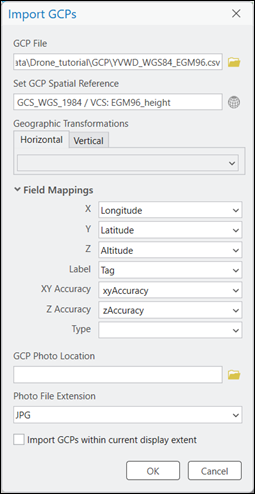
.The Import GCPs dialog box appears.
For GCP File, click the Browse button
 and browse to the location of the GCP file.
The GCP file can be a
.csvor.txtfile, feature class, or shapefile. The GCP file should include theLabel,X coordinate,Y coordinate,Z coordinate,XY accuracy, andZ accuracyfields.For Set GCP Spatial Reference, browse to and specify the horizontal and vertical coordinate systems of the GCPs.
If the coordinate system of the GCPs is different than that of the Reality mapping workspace, specify the horizontal and vertical geographic transformations to apply.
For Field Mappings, link the fields in the GCP file that correspond to the field mapping parameters listed.
For GCP Photo Location, if the GCP data includes photos of the locations where GCPs were measured, browse to and select the folder containing the photos.
The name of the photo must match the GCP
Labelfield value. If there are multiple photos for each GCP, the name of the photo must include a number appended to theLabelfield, which will be used as a unique identifier. For example,GCP20_1.jpgandGCP20_2.jpgare the photos for GCP20.Optionally, check the box to import only the GCPs that exist within the current display extent; otherwise, all GCPs are imported.
Click OK.
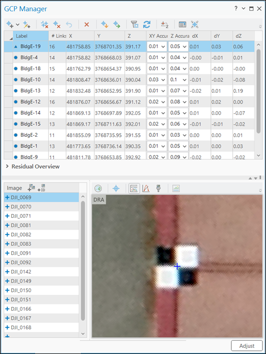
When the GCP’s have been imported into the GCP Manager, the list will be populated with the imported data.
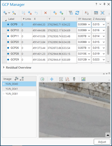
Click Adjust at the bottom of the GCP Manager window.
The Adjust dialog will open.
Perform the adjustment
The next operation performs the block adjustment, including the automatic detection of GCPs.
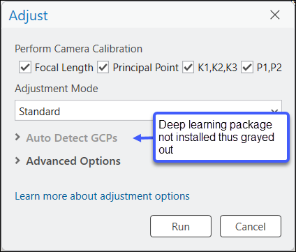
Accept the defaults for Perform Camera Calibration.
Choose Standard for Adjustment Mode if your imagery has medium to high contrast and development.
Note:
Use Challenging mode if your images have low contrast and texture, and little development.
Expand the Auto Detect GCPs section.
If Auto Detect GCP’s is inaccessible (grayed out), ensure the ArcGIS Deep Learning Package is installed.
Check the radio button next to Tag and re-adjust GCPs.
The GCP’s will be tagged, listed in the GCP Manager pane, and integrated in the adjustment.
Note:
If the quality of the premarks on the ground are questionable, and you would like to check the accuracy of the tagging, choose Tag GCPs. The GCP’s will be tagged but not adjusted.
Note:
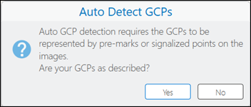
Upon checking a tagging option, a GCP requirement flag will be displayed. Click Yes.
For Tile Size and Number of Tie Points, accept or update the default values.
Note:
Number of Tie Points indicates the number of images in which the GCP will be tagged. The default value is five.
Accept all other defaults and click Run to facilitate the adjustment process.
Review the adjustment results based on the newly tagged GCPs in the GCP Manager.
Additional adjustment statistics are provided in the adjustment report. To generate the report, on the Reality Mapping tab, in the Review group, click Adjustment Report.