Line Of Sight (3D Analyst Tools)
Summary
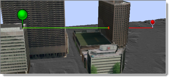
Determines the visibility of sight lines over obstructions consisting of a surface and an optional multipatch dataset.
Illustration
Usage
Only the endpoints of the input line will be used to define the observer and target. Sight lines should be straight lines composed of two vertices representing the observation point and the target location for which visibility will be determined.
Consider creating sight lines with the Construct Sight Lines tool if the visibility targets reside in a different feature class. For example, sight lines can be generated by sampling a target line feature at a specific interval to test the visibility along a path.
Output lines will be divided along visible and invisible portions of the input sight line. If only a surface is used to determine sight line visibility, the output lines will follow the surface profile. If a multipatch feature is provided when calculating line of sight, the output lines will follow the trajectory of the input sight lines.
The output line feature class will include the following fields:
SourceOID—The unique ID of the input line feature used in calculating visibility.VisCode—Indicates whether the output line represents a visible or nonvisible portion of the sight line. Each sight line may potentially be divided into multiple features based on whether the sight line is partially obstructed. This attribute identifies the visibility state of each portion of such sight lines. A value of 1 indicates the line is visible, and a value of 2 indicates it is not visible. This field will only exist in the output line features.TarIsVis—Indicates whether the target point is visible from the observer point. A value of 1 indicates the target is visible, and a value of 0 indicates it is not visible. This field will only exist in the output line features.OBSTR_MPID—The obstruction that blocks the visibility of the target point. A separate line feature will be created for the visible and obstructed portions of each input sight line. The portion that is not obstructed will have a value of -9999, the portion that is obstructed by a multipatch will have the unique ID of the obstructing feature, and the portion that is obstructed by the surface will have a value of -1.
If the Output graphing attributes parameter is checked, the output line feature class will have the following additional fields:
OBSERVERZ—The elevation of the observer point, which includes any vertical offset that may have been applied.TARGETZ—The elevation of the target point, which includes any vertical offset that may have been applied.OBSTR_DIST—The horizontal distance from the observer to the point that obstructs the visibility of the target. When the sight line is not obstructed, this value will be -1.0.
Parameters
| Label | Explanation | Data type |
|---|---|---|
|
Input Surface |
The integrated mesh scene layer, LAS dataset, raster, TIN, or terrain surface that will be used to determine visibility. |
TIN Layer; Raster Layer; Mosaic Layer; Terrain Layer; LAS Dataset Layer; Scene Layer; File |
|
Input Line Features |
The sight line features whose first vertex defines the observation point and last vertex identifies the target location. When the sight lines are 2D features, the observer and target heights will be derived from the input surface. When the sight lines are 3D features, the observer and target heights will be obtained from the feature's z-coordinates. 2D lines will be evaluated at an offset from the underlying surface. A default offset of 1 is applied to raise the points above the surface. For either 2D or 3D input lines, use a field named |
Feature Layer |
|
Output Feature Class |
The output line feature class along which visibility will be determined |
Feature Class |
|
Output Obstruction Point Feature Class (Optional) |
An optional point feature class identifying the location of the first obstruction on the observer's sight line to its target. |
Feature Class |
|
Use Curvature (Optional) |
Specifies whether the earth's curvature will be taken into consideration for the line-of-sight analysis. For this parameter to be enabled, the surface must have a defined spatial reference in projected coordinates with defined z-units.
|
Boolean |
|
Use Refraction (Optional) |
Specifies whether atmospheric refraction will be taken into consideration when generating a line of sight from a functional surface. This parameter does not apply if multipatch features are used.
|
Boolean |
|
Refraction Factor (Optional) |
The value that will be used as the refraction factor. The default value is 0.13. |
Double |
|
Pyramid Level Resolution (Optional) |
The z-tolerance or window-size resolution of the terrain pyramid level that will be used. The default value is 0, which is full resolution. |
Double |
|
Input Features (Optional) |
A multipatch feature that may define additional obstructing elements, such as buildings. Refraction options are not honored for this input. |
Feature Layer |
|
Output graphing attributes (Optional) |
Specifies whether the output sight line attributes will include additional fields with information that can be used in a profile graph. The values in these fields provide the information for generating a profile graph that includes a representation of the observer, potential obstruction, and the target point of each sight line, along with the visibility of the direct sight line that connects the observer to the target.
|
Boolean |
Environments
Current Workspace, Extent, Output Coordinate System, Geographic Transformations, XY Resolution, XY Tolerance, Output XY Domain, Z Resolution, Z Tolerance, Output Z Domain, Output CONFIG Keyword, Auto Commit, Minimize memory use during analysis on terrains
Licensing information
- Basic: Requires 3D Analyst
- Standard: Requires 3D Analyst
- Advanced: Requires 3D Analyst