Adjustment options for Reality mapping drone imagery
![]() Available with Advanced license.
Available with Advanced license.
![]() Available for an ArcGIS organization with the ArcGIS Reality license.
Available for an ArcGIS organization with the ArcGIS Reality license.
The parameters used in computing the block adjustment are defined in the Adjust window. The available adjustment options depend on the type of workspace defined when you set up the Reality mapping project. For example, triangulation is performed using EXIF data collected with drone imagery.
Adjustment options for drone data
Higher in-strip and cross-strip aerial image overlap is recommended for better block adjustment and product generation results. The block adjustment settings specific for drone imagery are described below.
Perform camera calibration
Automatic camera calibration computes and improves the camera’s geometric parameters, including interior orientation and lens distortion, while determining image orientation and image ground coordinates. If the camera has not been calibrated, as is the case of many cameras for collecting drone imagery, it is recommended that you check all the following options to improve the overall quality and accuracy of bundle block adjustment. All options are checked by default. For more information about calibration parameters, see Camera table schema.
Focal Length—Refines the focal length of the camera lens
Principal Point—Refines the principal point of the autocollimation
K1,K2,K3—Refines the radial distortion coefficients
P1,P2—Refines the tangential distortion coefficients
Camera calibration is performed during block adjustment to improve the camera parameter accuracy. For camera calibration, the image collection must have an in-strip overlap of 60 percent or more and a cross-strip overlap of 30 percent or more.
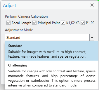
Adjustment Mode
When adjusting drone imagery there are two adjustment modes to choose from:
Standard—Recommended for images that have good contrast and are of areas comprised of sparse vegetation, medium to high percentage of human-made features, or small waterbodies. This is the default adjustment mode.
Challenging—Recommended for areas with large waterbodies, dense vegetation, sparse development features, low texture or low contrast. This mode is optimized to increase image correlation success in scenarios that are photogrammetrically challenging, and is more process intensive than Standard mode.
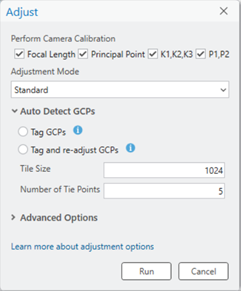
Automatically detect GCPs
Auto Detect GCPs enable the automatic detection and measurement of signalized ground control points (GCP) during the block adjustment process. The tool uses object detection functionality to identify and add tie points to a specified number of GCP overlapping images, and eliminating the need for manual measurements. The supported signalized GCP’s are checkers and crosses. Inputs to the tool include defining image tagging preferences, image chip size, and number of images to tag, or tie points to generate, per GCP. An explanation of each option is given below.
Tag GCPs—After adjustment, GCP’s will be automatically tagged (tie point added), but not integrated into the adjustment. As a result, you will not see a residual on the tagged GCP in the GCP Manager. Tagged GCP’s positioning can be reviewed and re-positioned if required. The Adjustment must be re-run to integrate the tagged GCP’s into the adjustment.
Tag and re-adjust GCPs—Following initial adjustment, GCP’s will be automatically tagged (tie point added), and integrated into the adjustment. As a result, you will see residuals (DX, DY, DZ) on the tagged GCP in the GCP Manager. If the GCP residuals are acceptable, you may proceed to derived product generation. If the residuals are not acceptable, the GCP’s and their positioning may be reviewed, repositioned if required and Adjust rerun to incorporate changes.
Tile Size—Defines the size if the image chips to be created to support GCP auto detection. The default value is 1024.
Number of Tie Points—Indicates the number of images in which the GCP will be tagged. The default value is five.
Note:
When re-running Adjust to either integrate changes or GCP’s that were only tagged, selecting a tagging option in Auto Detect GCPs section is not required. Reselecting a tagging option is only required if re-running Auto Detect GCP’s with different parameters.
Auto Detect GCPs option will be inactive if any of the following are true:
An Image Analyst or ArcGIS Reality for ArcGIS Pro license is not available.
The Deep learning package is not installed.
GCPs are not imported prior to running Adjust.
Advanced options
The Advanced Options section provides additional settings that can be used to optimize the adjustment process. A description of each optional setting is given below.
Quick adjust at coarse resolution only
If this option is checked, adjustment will be performed at a coarse, user-defined resolution. This coarse adjustment is done quickly and allows you to review the data coverage for your project area and the processing parameters for the collection before running the more accurate, refined adjustment at the source image resolution. For example, when you collect data in the field, you can use this option for an initial assessment of the adjustment and run Adjust again to compute the refined adjustment. If this option is not checked, tie points are computed at source image resolution, and triangulation is performed using the computed tie points.
Use orientation from metadata
When checked, the exterior orientation information embedded within the image EXIF will be used as initial values in the block adjustment process.
Fix image location for high accuracy GPS
This option is used only for imagery acquired with high-accuracy, differential GPS, such as real-time kinematic (RTK) or post processing kinematic (PPK). If this option is checked, the process will only adjust the orientation parameters of the imagery and leave GPS measurements fixed. Additionally, ground control points (GCPs) are not required when this option is checked. GCPs will be marked as check points in the adjustment.
Compute posterior standard deviation for images and solution points
The following options allow users to compute the standard deviation for each image exterior orientation parameters and solution point coordinates.
Compute Posterior Standard Deviation for Images—The posterior standard deviation of solution points after adjustment will be computed. The computed standard deviation values will be stored in the Solution table.
Compute Posterior Standard Deviation for Solution Points—The posterior standard deviation of each image location and orientation after adjustment will be computed. The computed standard deviation values will be stored in the Solution Points table.
Reproject tie points
A part of the adjustment process includes computing and displaying each tie point at its correct 2D map location. This is an optional step that only supports the visual analysis of tie points with the 2D map view. Following adjustment, the Reproject Tie Points option in the Manage Tie Points drop-down menu must be used.
Note:
When working with large projects with more than 1,000 images, this step can be skipped to reduce adjustment processing duration, without any adverse impact to the adjustment quality.
Rolling shutter mode
Check the Rolling Shutter Mode option if the images being processed were captured using a rolling shutter camera.
Tie point matching
Tie points are points that represent common objects or locations within the overlap areas between adjacent images. These points are used to improve geometric accuracy in the block adjustment. The Tie Point Matching category in the Adjust tool includes options to support the automatic computation of tie points from overlapping images.
Image resolution factor
The Image Resolution Factor parameter is used to define a resolution at which match points are computed and the initial adjustment is performed. The range of values is between full resolution and 8 times the resolution of the source imagery.
The default value of 8 times the source image resolution is suitable for most imagery that includes a diverse set of features. A smaller value such as 4 or 2 can be used for imagery with ubiquitous features, such as sand, water, or agricultural areas, where match points are difficult to compute at coarser resolution.
Image location accuracy
Image location accuracy indicates the accuracy level of the GPS data collected concurrently with the imagery and listed in the corresponding EXIF data file. The values consist of four airborne GPS accuracy levels that are used in tie point calculation to determine the number of necessary overlapping images. For example, when the accuracy is set to High, the algorithm uses a smaller neighborhood to identify matching features in the overlapping images.
|
Setting |
Description |
|---|---|
|
High |
The GPS accuracy is 0 to 10 meters. A maximum of 4 x 3 images are used for tie point matching. This is the default setting. |
|
Medium |
The GPS accuracy is 10 to 20 meters. A maximum of 4 x 6 images are used for tie point matching. |
|
Low |
The GPS accuracy is 20 to 50 meters. A maximum of 4 x 12 images are used for tie point matching. |
|
Very Low |
The GPS accuracy is more than 50 meters. A maximum of 4 x 20 images are used for tie point matching. |
The Image Location Accuracy setting is used only to support tie matching and generation, and does not signify adjustment accuracy.
Mask polygon features
Use a polygon feature class to exclude areas you do not want used when computing tie points.
In the attribute table of the feature class, the Mask field controls the inclusion or exclusion of areas for computing tie points. A value of 1 indicates that the areas defined by the polygons (inside) are excluded from the computation. A value of 2 indicates that the areas defined by the polygons (inside) are included in the computation and areas outside of the polygons are excluded.
Drone imagery tutorial
For a tutorial on the complete drone imagery workflow, see Tutorial: Create drone imagery products in ArcGIS Reality for ArcGIS Pro.