Detect Dark Ocean Areas (Image Analyst Tools)
Summary
Identifies potential dark pixels belonging to oil spills or algae, and clusters these pixels, while masking out the synthetic aperture radar (SAR) data outside the region of interest.
The tool filters clusters using the Minimum Area parameter, and creates the result as a binary raster. A value of 1 corresponds to dark areas detected and is symbolized in a random color. A value of 0 indicates that no dark areas were detected and is symbolized with full transparency.
Both orthorectified and nonorthorectified radar data are valid inputs. Nonorthorectified radar data results in improved azimuth artifact filtering, since the data is in radar coordinates.
Usage
Optimize area detection by calibrating the input radar data to gamma nought using the Apply Radiometric Calibration tool. This is especially effective in larger radar scenes.
To ensure that only areas in the ocean are detected, provide a value for the Mask Features parameter and use the Feature Type parameter to specify whether the mask is water or land. Alternatively, provide a DEM Raster parameter value, and the tool will use the elevation to determine land and water pixels. Either of these methods can be used to create a land mask.
If both the Mask Features and DEM Raster parameter values are provided, the Mask Features parameter will be used to create the mask.
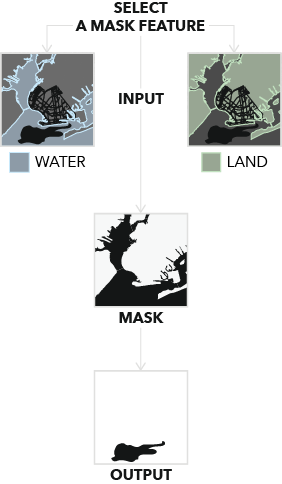
Water and land masks for dark ocean areas are shown.
Parameters
| Label | Explanation | Data type |
|---|---|---|
|
Input Radar Data |
The input radar data. |
Raster Dataset; Raster Layer |
|
Output Raster |
The output binary raster of the detected dark ocean areas. A value of 1 corresponds to a detected dark area. |
Raster Dataset |
|
Minimum Area (Optional) |
The minimum area to be detected. The size cannot be negative. The default value is 10000 square meters. |
Areal Unit |
|
Mask Features (Optional) |
A land or water polygon feature. This polygon will be used to create a mask. |
Feature Layer |
|
Feature Type (Optional) |
Specifies the type of polygon the Mask Features parameter value represents. This parameter is required if the Mask Features parameter value is provided.
|
String |
|
DEM Raster (Optional) |
The input DEM. If a Mask Features parameter value is provided, this DEM will be used to project it in radar coordinates. If no value is provided for the Mask Features parameter, this DEM will also be used to create a land mask. |
Mosaic Layer; Raster Layer |
|
Apply Geoid Correction (Optional) |
Specifies whether the vertical reference system of the input DEM will be transformed to ellipsoidal height. Most elevation datasets are referenced to sea level orthometric height, so a correction is required in these cases to convert to ellipsoidal height.
|
Boolean |
|
Mask Tolerance (Optional) |
The buffer distance surrounding the mask created from either the Mask Features parameter or the DEM Raster parameter. The distance cannot be negative. The default value is 100 meters. |
Linear Unit |
Environments
Compression, Current Workspace, NoData, Parallel Processing Factor, Pyramid, Raster Statistics, Resampling Method, Scratch Workspace, Tile Size
Licensing information
- Basic: Requires Image Analyst
- Standard: Requires Image Analyst
- Advanced: Requires Image Analyst