Tutorial: Create 2D digital aerial imagery products in ArcGIS Pro using ArcGIS Reality Server
![]() Available with Standard or Advanced license.
Available with Standard or Advanced license.
In ArcGIS Pro, you can connect to ArcGIS Reality Server and photogrammetry correct digital aerial imagery collected by a professional mapping camera to remove geometric distortions caused by the sensor and terrain displacement. After correcting these effects, you can generate Reality mapping products.
In this tutorial, you will set up a Reality mapping workspace to manage an aerial imagery collection. You will perform a block adjustment and review the results. Then you'll generate digital surface model (DSM), digital terrain model (DTM), true ortho, and DSM mesh products.
Computing the photogrammetric solution for aerial imagery is determined by its exterior orientation (EO), which represents a transformation from the ground to the camera and its interior orientation (IO), which represents a transformation from camera to image. Required EO parameters include perspective center (x,y,z) coordinates, and omega, phi, and kappa angles are provided in a frames table. Interior orientation parameters include focal length, pixel size, principal point, and lens distortion. This information is available in the camera calibration report associated with the imagery and must be provided in a camera table.
Note:
ArcGIS Reality Server is needed to complete this tutorial. To configure a Reality Server, please refer to the Reality Server installation.
Connect to ArcGIS Reality Server
To utilize Reality Server for processing your data in ArcGIS Pro, you need to first connect to the Reality Server.
Open ArcGIS Pro, Click the Project tab on the ribbon and click the Portals page.
You can also access the portals page from the Manage Portals link in the Sign In menu
 .
.Click Add Portal.
Enter the URL (
https://webadaptorhost.domain.com/webadaptorname) for the portal on the Add Portal dialog box and click OK.Sign in to the portal by clicking the Options button
 or right-click the portal and click Sign in. Enter your username and password.
To make the new connection your active portal, right-click the URL and click Set As Active Portal.
Once you successfully connect to your portal, your username will show up in the top right corner of ArcGIS Pro.
Create a Reality mapping workspace
A Reality mapping workspace is an ArcGIS Pro subproject that is dedicated to Reality mapping workflows. It is a container in an ArcGIS Pro project folder that stores the resources and derived files that belong to a single image collection.
A collection of digital aerial images is provided for this tutorial. The tutorial data also contains frame and camera tables.
To create a Reality mapping workspace, complete the following steps:
Download the tutorial dataset and save it to
C:\SampleData\Aerial Imagery.If you save the data to a different location on your computer, update the path in each of the entries in the
Nadir_FramesCam.csvfile.- Unzip the package in the
C:\SampleData\Aerial Imagerydirectory.
- Unzip the package in the
In ArcGIS Pro, create a project using the Map template.
On the Imagery tab, in the Reality Mapping group, click the New Workspace drop-down menu and choose New Workspace.
In the Workspace Configuration window, provide a name for the workspace.
Set Workspace Type to Reality Mapping.
In the Sensor Data Type drop-down menu, choose Aerial - Digital.
Set Scenario Type to Nadir.
This setting is recommended when working with nadir imagery.
In the Basemap drop-down menu, choose Topographic.
Set the Parallel Processing Factor.
This controls the maximum computational resource for distributed processing. It is recommended to use percentage expression. For example, if you have 2 Reality Server nodes, set Parallel Processing Factor to 50% to utilize one machine for block adjustment and reality mapping product generation.
Check Process this image collection on server if you want to use Reality Server.
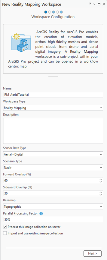
Accept all other default values and Click Next.
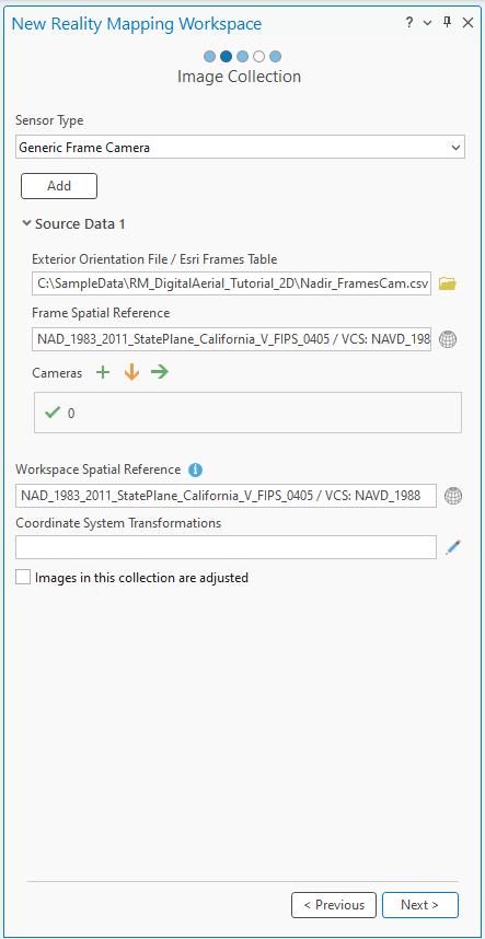
The Image Collection window appears.
In the Image Collection window, under Exterior Orientation File / Esri Frames Table, browse to the tutorial data folder on your computer and the
Nadir_FramesCam.csvframes table file.This table, which contains the frames and cameras information, specifies parameters that are used to compute both the IO and EO for the camera and the imagery. In the block adjustment process, these approximate values are refined for greater accuracy.
Ensure that the data paths listed in the
rastercolumn in the frame table file match the location of the image files on your computer.Under Cameras, click the Import button
 , browse to the tutorial data folder on your computer, and select the
 Nadir_FramesCam.csvfile.For this tutorial, the Esri frame and camera tables are provided as a single file in the proper format. For other datasets, you may need to build and format the tables. For more information, see Frames table schema.
Ensure that the Spatial Reference and camera model values are correct.
The default projection for the workspace is defined based on the imagery. This projection must match the coordinates used in the frames table, and it determines the spatial reference for the Reality products you create. For this dataset, you’ll use the projection defined in the frames and cameras table: XY – NAD83 2011 StatePlane California V FIPS 0405, VCS NAVD88 (meters).
Accept the other default values and click Next.
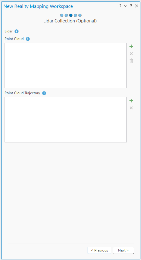
In the Lidar Collection window, accept the default values and click Next.
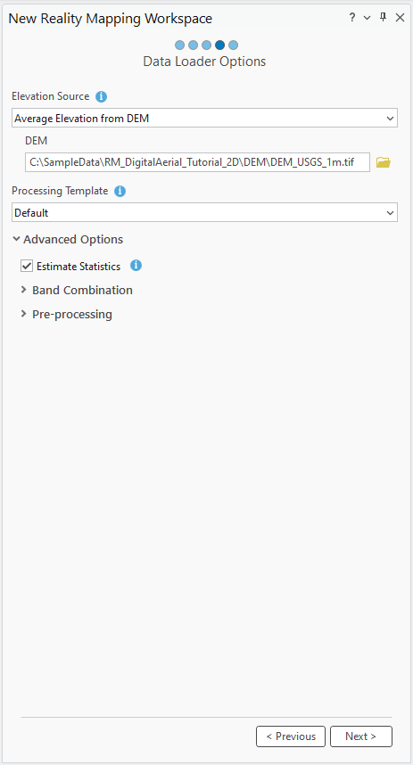
In the Data Loader Options window, under DEM, click the browse button, browse to the tutorial data folder on your computer, and select the
DEM_USGS_1m.tiffile.Accept the other default values and click Finish.
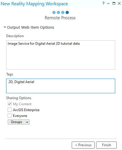
In the Remote Process window, provide description and tags for the image service and click Finish.
Once the workspace has been created, a Reality Mapping category will be added to the Contents pane, where the image collection image service and derived Reality mapping products service will be stored.
To see the image footprints, you can right click on the Image Collection in the Contents pane > Properties > Display > Check on Display Footprints.
The initial display of imagery in the workspace confirms that all images and necessary metadata were provided to initiate the workspace. The images have not been aligned or adjusted, so the mosaic may not appear geometrically correct.
Note:
You may need to zoom in close enough to see the image.
A new Reality Mapping tab will be added to the ArcGIS Pro main menu. Clicking this tab will expose a series of tools and workflows dedicated to Reality mapping. In the Product category, all the buttons are unavailable because the images are not yet adjusted.
Perform a block adjustment
After you create the Reality mapping workspace, the next step is to perform a block adjustment using the tools in the Adjust and Refine groups. The block adjustment will calculate tie points, which are common points in areas of image overlap. The tie points will then be used to calculate the orientation of each image, known as exterior orientation in photogrammetry.
To perform a block adjustment, complete the following steps:
On the Reality Mapping tab, in the Adjust group, click Adjust
 .
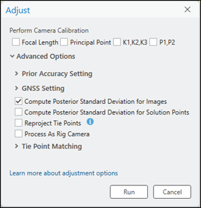
.Perform Camera Calibration is not checked by default for digital aerial nadir imagery, as most airborne sensors have been calibrated and provide accurate interior orientation values in a camera calibration report. Automatic camera calibration is typically applied to other types of data, such as low-cost drone cameras, to compute and improve the camera’s geometric parameters while simultaneously determining image orientation and image ground coordinates.
Accept the default values for all the settings and click Run.
On the Reality Mapping tab, in the Review group, click Logs View
 .
.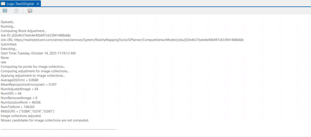
The units for tie point RMS error is pixels.
Review the adjustment results
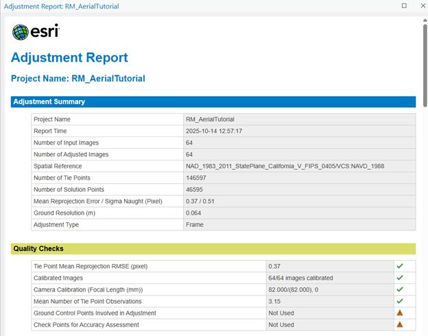
After performing a block adjustment, review the adjustment results and assess the quality of the adjustment. On the Reality Mapping tab, in the Review group, click Adjustment Report to generate adjustment statistics. The adjustment report provides a record of the adjustment and overall quality measures of the process.
Tip:
Using ground control points (GCPs) to improve the absolute accuracy is a best practice. However, GCPs were not available and are not included in this adjustment.
Generate Reality mapping products
Once the block adjustment is complete, 2D and 3D imagery products can be generated using the tools in the Product group on the Reality Mapping tab. Multiple products can be generated simultaneously using the Reality Mapping Products wizard or individually by selecting the applicable product tool from the Product group. The types of products that can be generated depends on various factors including the sensor, data flight configuration, and scenario type. The flight configuration of the sample dataset is nadir, which is ideal for 2D products such as DSM, true ortho, and DSM mesh.
Note:
In this tutorial, two approaches to generate derived products are described below. One approach uses the Multiple Products wizard and the second uses the individually named product wizards listed in the Product group. It is recommended that you follow one or the other workflow approach, since doing both workflows is not required for this tutorial.
Generate products using the Reality Mapping Multiple Products wizard
The Reality Mapping Products wizard guides you through the workflow to create one or multiple Reality mapping products in a single process. The products that can be generated using the Reality Mapping Multiple Products wizard are DSM, true ortho, DSM mesh, point cloud, and 3D mesh. All generated products are stored in product folders of the same name under the Reality Mapping category in the Catalog pane.
To generate products using the Reality Mapping Multiple Products wizard, complete the following steps:
On the Reality Mapping tab, click the Multiple Products button in the Product group.
The Reality Mapping Products Wizard window appears.
In the Product Generation Settings pane, uncheck the 3D check box.
In this tutorial, only 2D products are generated.
In the 2D products category, uncheck Digital Terrain Model (DTM).
DTM generation will be covered in a separate tutorial.
Click the Shared Advanced Settings button.
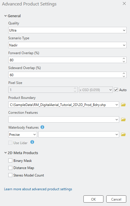
The Advanced Products Settings dialog box appears, where you can define parameters that will impact the Reality mapping products to be generated. For details of the advanced product settings, see Shared Advanced Settings option.
The Quality and Scenario values are automatically set to Ultra and Nadir, respectively, and should not be changed to ensure optimum performance and product quality.
Accept the Pixel Size default settings to generate products at source image resolution.
Change the Forward Overlap (%) and Sideward Overlap (%) values to 80 and 60, respectively.
For Product Boundary, click the Browse button
 , browse to the file geodatabase in the tutorial data location, select
 2D_Pro_bdry, and click OK.It is recommended that you provide a product boundary for the following reasons:
Define the proper output extent—When you do not define a product boundary, the application automatically defines an extent based on various dataset parameters that may not match the project extent.
Reduce processing time—If the required product extent is smaller than the image collection extent, defining a product boundary reduces the processing duration and automatically clips the output to the boundary extent.
Accept all the other default values and click OK.
The Advanced Products Settings dialog box closes, and you return to the Product Generation Settings pane in the Reality Mapping Products wizard.
Click Next to go to the DSM Settings pane, and ensure that the parameter values match the following:
Output Type: Mosaic
Resampling: Bilinear
Click Next to go to the True Ortho Settings pane, and ensure that the parameter values match the following:
Output Type: Mosaic
Resampling: Bilinear
Click Next to go to the DSM Mesh Settings pane and accept the default options.
Click Finish to start the product generation process.
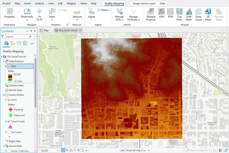
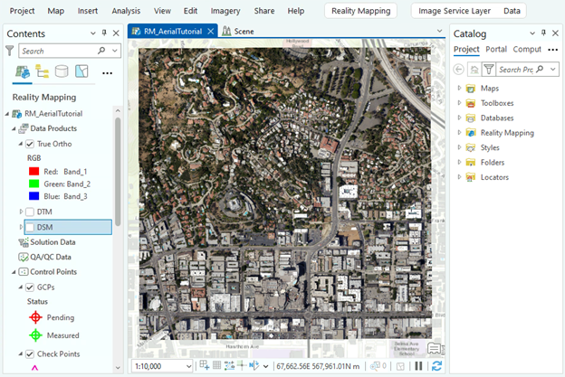
Once product generation is complete, the DSM, DTM and true ortho products are automatically added to the 2D map view. In the Catalog pane, in the Reality Mapping container, the DSM mesh products are added to the Meshes folder, and the true ortho products are added to the Ortho folder. To visualize the generated DSM mesh product, right-click the DSM Mesh for RM_AerialTutorial in the Meshes folder, and from the drop-down menu, click Add to New > Local Scene.
You can end the tutorial now or continue to generate derived products using the individual product options in the Product group. If you continue, previously generated products will be overwritten. To maintain previously created products, follow the instructions in the Create a Reality mapping workspace section above to create a new Reality mapping workspace before proceeding.
Generate a DSM
To generate a DSM using the Reality Mapping Products wizard, complete the steps below.
Note:
Elevation values can be derived when the image collection has a good amount of overlap to form the stereo pairs. Typical image overlap necessary to produce point clouds is 80 percent forward overlap along a flight line and 60 percent overlap between flight lines.
On the Reality Mapping tab, click the DSM button
 in the Product group.
The Reality Mapping Products Wizard window appears.
Click Shared Advanced Settings.
The Advanced Product Settings dialog box appears, where you can define parameters that will impact the Reality mapping products to be generated.
The Quality and Scenario values are automatically set and should not be changed to ensure optimum performance and product quality. However, if you want to generate a reduced resolution product, the Quality value can be lowered. See Shared Advanced Settings option for more information about the impact of various quality settings on product generation.
Accept the Pixel Size default values to generate products at source image resolution.
Change the Forward Overlap (%) and Sideward Overlap (%) values to 80 and 60, respectively.
For Product Boundary, select a feature class identifying the output product extent from the drop-down list, or click the Browse button
, browse to the file geodatabase in the tutorial data location, select 2D_Pro_bdry, and click OK.It is recommended that you provide a product boundary for the following reasons:
Define the proper output extent—When you do not define a product boundary, the application automatically defines an extent based on various dataset parameters that may not match the project extent.
Reduce processing time—If the required product extent is smaller than the image collection extent, defining a product boundary reduces the processing duration and automatically clips the output to the boundary extent.
Accept all the other default values and click OK.
The Advanced Products Settings dialog box closes and you return to the Products Generation Settings pane in the Reality Mapping Products wizard.
Click Next to go to the DSM Settings pane, and ensure that the parameter values match the following:
Output Type—Mosaic
Resampling—Bilinear
Click Finish to start the product generation process.
Once processing is complete, the DSM product is added to the Contents pane, the Data Products category, and the 2D map view. It is also added to the Catalog pane, the Reality Mapping container, and the DEMs folder.
Generate a DTM
A digital terrain model (DTM) is a bare-earth digital elevation dataset, with above-ground objects, such as trees and buildings, filtered out.
To generate a DTM, complete the following steps:
On the Reality Mapping tab, click the DTM button
 in the Product group.
The Reality Mapping Products Wizard window appears.
Click Shared Advanced Settings.
The Advanced Product Settings dialog box appears, where you can define parameters that will impact the Reality mapping products to be generated. For details of the advanced product settings, see Shared Advanced Settings option.
Complete steps 3 through 6 in the Generate a DSM section above.
Click Next to go to the DTM Settings pane.
For Ground Detection Method, choose the Standard option.
Keep Reuse Existing Ground unchecked for the first time you create the DTM.
Check the Classify Low-noise Points box.
Leave Preserve Existing Low-noise Points unchecked for the first time you create the DTM.
Optionally, set a value for Minimum Depth Below Ground. Points with distance below ground larger than this value will be classified as low-noise points. The Minimum Depth Below Ground default value is 0.25 meters.
Check the Classify High-noise Points box.
Leave Preserve Existing High-noise Points unchecked the first time you create the DTM.
Optionally, set a value for Minimum Height Above Ground. Points with distance above the ground larger than this value will be classified to be high-noise points. The minimum Height Above Ground default value is 100 meters.
Expand DTM Interpolation to see all the available options. We will accept all default values in this tutorial.
Click Finish to start the product generation process.
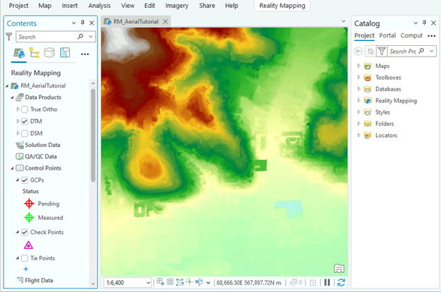
Once processing is complete, the DTM product is added to the Contents pane, the Data Products category, and the 2D map view. It is also added to the Catalog pane, the Reality Mapping container, and the DEMs folder.
Generate a true ortho
One of the options in the Reality mapping Product group is True Ortho. A true ortho is an orthorectified image with no perspective distortion so that above-ground features do not lean and obscure other features. To create a true ortho, a DSM derived from the adjusted block of overlapping images is required. As a result, a DSM will be generated as a part of the true ortho process regardless of whether a DSM was previously selected as a product. The generated true ortho image will be stored in the Orthos folder under the Reality Mapping category in the Catalog pane.
To generate a true ortho using the Reality Mapping Products wizard, complete the following steps:
On the Reality Mapping tab, click the True Ortho button
 in the Product group.
The Reality Mapping Products Wizard window appears.
Click Shared Advanced Settings.
The Advanced Product Settings dialog box appears, where you can define parameters that will impact the Reality mapping products that you generate. For a detailed description of the advanced product settings, see Shared Advanced Settings option.
Complete steps 3 through 6 in the Generate DSM section above.
Click Next to go to the True Ortho Settings pane, and ensure that the parameter values match the following:
Output Type: Mosaic
Resampling: Bilinear
NoData Value: None
Click Finish to start the product generation process.
Once processing is complete, the true ortho product is added to the Contents pane, the Data Products category, and the 2D map view. It is also added to the Catalog pane, the Reality Mapping container, and the Ortho folder.
Generate a DSM mesh
A DSM mesh is a 2.5D textured model of the project area where the adjusted images are draped on a triangulated irregular network (TIN) version of the DSM extracted from the overlapping images in the adjusted block. The Reality Mapping Products wizard simplifies the creation of the DSM mesh product by providing a streamlined workflow with preconfigured parameters. To create a DSM mesh product, a DSM derived from the adjusted block of overlapping images is required. As a result, a DSM is generated as a part of the DSM mesh generation process whether or not a DSM was selected as a separate product.
To generate a DSM mesh using Reality Mapping Products wizard, complete the following steps:
On the Reality Mapping tab, click the DSM Mesh button
 in the Product group.
The Reality Mapping Products Wizard window appears.
Click Shared Advanced Settings.
The Advanced Product Settings dialog box appears, where you can define parameters that will impact the Reality mapping products that you generate. For a detailed description of the advanced product settings, see Shared Advanced Settings option.
Complete steps 3 through 6 in the Generate DSM section above.
Click Next to go to the DSM Mesh Settings pane.
Accept the default values and click Finish to start the product generation process.
Once processing is complete, the DSM mesh product is added to the Catalog pane, the Reality Mapping container, and the Meshes folder.
To visualize the generated DSM mesh product, right-click the
3D_Mesh.slpkfile in the Meshes folder, and from the drop-down menu, click Add to New > Local Scene.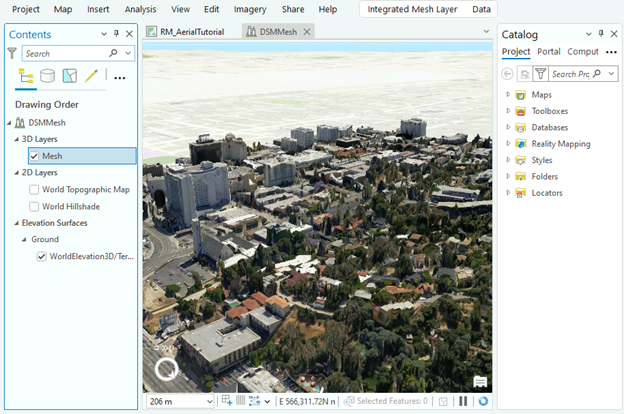
Summary
In this tutorial, you created a Reality mapping workspace for nadir digital aerial imagery and used tools on the Reality Mapping tab to apply a photogrammetric adjustment in Pro using Reality Server. You then used tools in the Products group to generate DSM, DTM, true ortho, and DSM mesh products.