Circuit diagrams and their specifics
A utility network designed for a telecommunication industry is generally composed of telecom domain networks with defined circuits. Each circuit represents a signal path between specified elements in a telecom domain network. This signal path passes through various complex network elements that can not be represented on the network map. For telecom circuits, circuit diagrams allow users to clearly visualize the components along each circuit.
Circuit diagrams
A circuit diagram is a network diagram representing a circuit in a telecom domain network. The best way to generate such a diagram in ArcGIS Pro is to work from the Find Circuits pane. The building process to generate circuit diagrams is different from the one to generate subnetwork system diagrams or standard diagrams. It needs a diagram template as for any network diagram creation, but expects a string name as an input. This name must correspond to a defined circuit name in a telecom domain. Then, the creation is controlled by specific settings expected on the related template.
Learn more about the specifics for circuit diagram templates
Create circuit diagrams
To create a circuit diagram, you can apply the following workflow steps:
Start ArcGIS Pro and open a utility network project.
Open any map that already references the utility network layer or create a map and add the utility network to it.
Review the general network diagram options that are currently set, and depending on the purpose of the diagram you are going to create, consider checking the Open diagrams with all diagram template sublayers option.
Click the Utility Network tab on the ribbon and click the Find Circuits command
 in the Telecom Circuits group.
Note:
The Telecom Circuits group is enabled only when a utility network that contains a telecom domain network is in the active map.
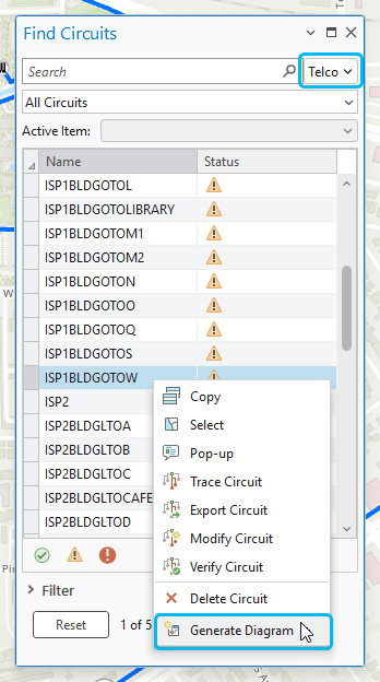
On the top of the Find Circuits pane window that opens, from the dropdown list at the right of the Search area, choose the telecom domain network you want to work with.
All the circuits existing for the chosen telecom domain network display in the pane.
Right click a circuit in the list and click Generate diagram.
Important:
The Generate diagram item menu is only available when a circuit diagram template is associated with the active telecom domain.
The circuit diagram opens in a new diagram map which name corresponds to the circuit name.
Create a new circuit diagram from an open circuit diagram
The Find Circuits pane allows you to interact with telecom circuits when the utility network is present in the active map. These interactions are also supported from active network diagram maps. You can select a diagram feature in the active diagram map, and select one of the the prepopulated filters from the drop-down menu—All Circuits, Circuits starting from selected feature/object, Circuits ending on selected feature/object, Circuits passing through selected feature/object, Deleted Circuits. Then, you can right click any circuit listed on the grid to display the context menu, and click Generate diagram to generate another circuit diagram. With such interactions, you can easily navigate from a circuit diagram to another.