Rule and layout definitions specifics for circuit diagram templates
Circuit diagrams are managed by specific templates. The process to build circuit diagrams is also a little bit different from standard diagrams and subnetwork system diagrams.
Circuit diagram template settings
A circuit diagram template has two special characteristics:
It is associated with a specific telecom domain
It includes a Trace rule configured to run a Circuit trace type
Those two settings are mandatory for circuit diagram templates. Also, as the other diagram templates, they support the following configurations:
Diagram rules to simplify the circuit; for example, Collapse Container or Reduce Junction rules.
Such rules can be set up after the Trace rule. In all cases, there is no point in configuring any diagram rule before the Trace rule; they will always be ignored during the circuit diagram generation process.
Diagram layouts; for example, Smart Tree layout
Layouts can be configured to automatically apply at the end of the diagram generation process.
The sections below highlight the minimum settings expected for circuit diagram templates.
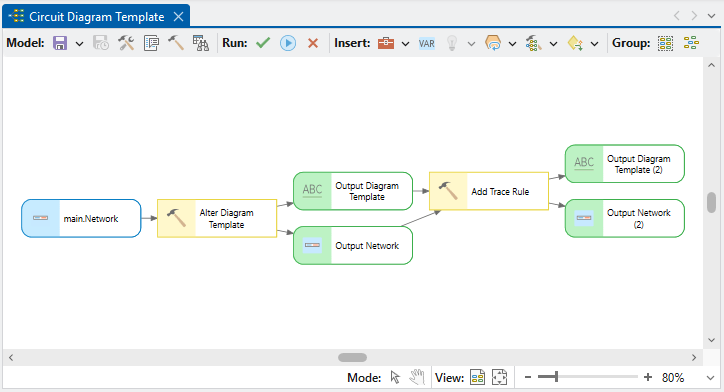
Circuit diagram template geoprocessing model
The geoprocessing model used to set up such a diagram template can be configured using two network diagram configuration tools: Alter Diagram Template tool and Add Trace Rule tool.
Alter Diagram Template tool settings
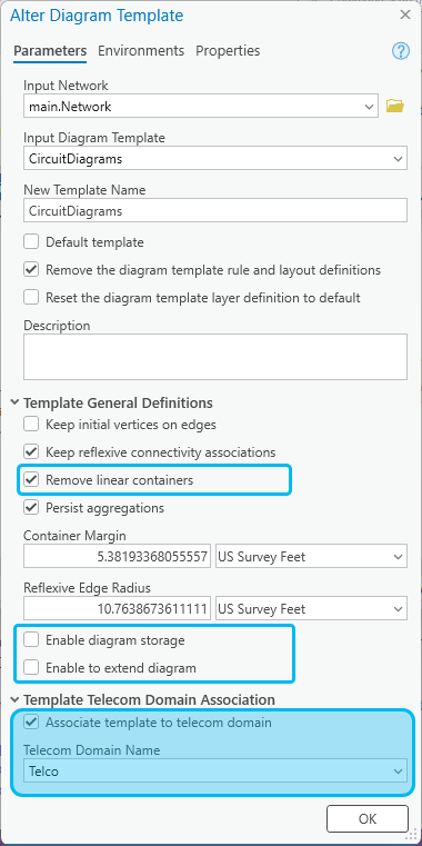
The settings in the Template Telecom Domain Association section are key settings that determine whether the Generate diagram menu item is available in the Find Circuits pane.
The Associate template to telecom domain option must be turned on.
The name of the telecom domain network to which the template applies must be selected in the Telecom Domain Name list.
The other options as shown in the graphic above are recommended settings for obtaining better circuit diagrams. Special mention for three of them:
Remove linear containers option—To turn on for an easy removal of all linear containers that are included by default during diagram building.
Enable diagram storage option—To turn off since there is no reason to store any circuit diagrams.
Enable to extend diagram option—To turn off since extending a circuit diagram doesn't make sense. Moreover, Extend Diagram and Append to Diagram processes are incompatible with the way circuit diagrams are generated.
Add Trace Rule tool settings
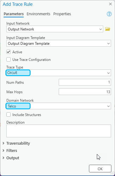
The trace rule to generate circuit diagrams must be configured to run the Circuit trace type and specify the name of the telecom domain network on which the trace will apply.
The other rule settings are the default.
Important:
The name specified for the Domain Network on the Add Trace Rule tool must correspond to the Telecom Domain Name set for the Alter Diagram Template tool.
Circuit diagram building process
The diagram generation process for circuit diagram works in the following ways
Starting from the name as input, it analyzes the associated template settings and search for a Trace rule.
If the detected trace rule is configured to apply a Circuit trace on a particular telecom domain network and the input name corresponds to a circuit name defined along this telecom domain network, it traces this circuit, and builds a first in-memory diagram graph composed of all the components along the traced circuit. This diagram graph can include pure schematic edges representing implicit connections between sections or between contained network elements along the traced circuit.
Important:
When there is no trace rule configured for the associated template, the generated diagram is empty. When a trace rule exists but it doesn't apply the Circuit trace type, the diagram generation fails.
Then, the diagram building continues in the same way as for any other diagrams:
If other diagram rules exist on the associated template, they apply each-in-turn in the order they have been configured to progressively modify the diagram graph in memory.
If active diagram layout exists on the associated template, they apply each in turn in their entry sequence order to lay out the diagram content.
At the end of the build, the diagram opens in a new diagram map.
Note:
The diagram layer definition must include the Inferred Connectivity and Virtual Connectivity schematic edge layers to properly show the implicit connections between sections or between contained network elements along the traced circuits. See Schematic Edges option in the Create Diagram Layer Definition tool.