Telecom domain networks
Workflows and storage models in the telecommunications industry are distinct from other utility domains. Unlike traditional domain networks, the telecom domain network is designed to handle the complexities associated with managing a large number of features and to support advanced circuit modeling requirements associated with telecom operations.
Telecom domain networks diverge from traditional domain networks in that they employ circuit management tables in the schema, which allow you to model and manage the collection of components that represent a dedicated path between elements in the network. This domain network type does not support subnetwork management but instead employs various tools and commands that allow you to manage circuits in your network.
The telecom domain network supports the concept of grouping on junction objects, edge objects, and associations. This allows you to model a logical collection of rows that share a topology and attribution using a single record. For example, a single grouped edge object can be used to model all 96 fiber strands in a single fiber cable using a grouping schema that communicates information on the range of units such as where the group begins (First unit) and ends (Last unit) to communicate the number of entities in the group.
Learn more about how to work with unit identifiers
Classes in a telecom domain network
When a telecom domain network is added to a utility network, attribute fields are added to the nonspatial junction and edge objects and Associations table to support grouping, color schemes, and foreign key based associations. Circuit management tables are created to manage your circuits, and a dirty objects table is created to manage the status of nonspatial objects and associations in the domain network.
Each telecom domain network consists of four feature classes (Device, Line, Junction, and Assembly) and five tables (JunctionObject, EdgeObject, Circuit, CircuitSection, and Subcircuit) that are created when you create a telecom domain network using the Add Telecom Domain Network tool. These classes contain a different schema than those in a traditional domain network and are created with system-provided attribute domains assigned to system fields for use by the utility network. Additional configuration is required to use these fields.
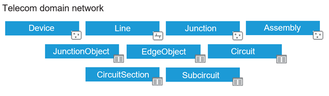
The four feature classes are described as follows:
Device—Represents equipment point features such as a switch, optical network terminal, or antenna. These are compact features through which resources flow and interact. For example, a switch identifies the target of a request and controls the routing of data, and an optical network terminal converts the signal from fiber into a usable form for devices. Devices can be connected to other devices, junctions, and lines. Devices can be contained in assemblies and in structure junctions, structure lines, or structure boundaries, which are containers. Devices can also contain other features and objects in the network. When assigned the Junction Unit Container category, they can be used to manage unit identifiers (Unit IDs) on grouped objects assigned as Unit Identifiable through the
Next unit IDattribute field.Line—Represents linear features such as cables or wireless paths. These are the lines through which your resource is delivered. When assigned the Edge Unit Container category, they can be used to manage Unit IDs on grouped objects assigned as Unit Identifiable through the
Next unit IDattribute field. Features assigned the Edge Unit Container category constrain the number of units for features in their containment hierarchy using theMax content unit IDfield.Junction—Represents locations where lines connect to lines through features such as a slack loop, splice closure, or riser. A key use of junction features is to allow devices or lines to connect to another line at a midspan vertex. Junctions are placed as needed to complete the connection of all the features in a network.
Assembly—Represents equipment that contains other devices, junctions, and lines. This is used when you want to model the internals of equipment using spatial features. As with device features, assembly features are compact features, but they differ in that assemblies contain other significant devices. Assemblies are useful to show a single symbol on the map yet model the internal features and their connections. You can view the internal features of an assembly on the map or in the diagram view. Potential examples of assembly features are patch panels or splitters.
The five tables are described as follows:
JunctionObject—Represents nonspatial junction objects such as chassis, ports, or splices that are contained within devices, junctions, or other network features. Junction objects can also contain other junction objects. When assigned the Junction Unit Container category, they can be used to manage unit identifiers on grouped objects assigned as Unit Identifiable through the
Next unit IDattribute field.EdgeObject—Represents nonspatial edge objects such as copper strands, fiber strands, or wireless signals contained within a line. Edge objects can also contain other features and objects. When assigned the Edge Unit Container category, they can be used to manage unit identifiers on grouped objects assigned as Unit Identifiable through the
Next unit IDattribute field. Objects assigned the Edge Unit Container category constrain the number of units for features in their containment hierarchy using theMax content unit IDfield.Circuit—System-maintained circuit management table containing the uniquely named circuits in the telecom domain network.
CircuitSection—System-maintained circuit management table that stores information on the collection of locations for sections that compose the circuits. Each record of this table represents a collection of locations (starting point, stopping point, barrier or subcircuit) used in the section.
Subcircuit—System-maintained circuit management table that represents how circuits are subdivided to define another circuit.
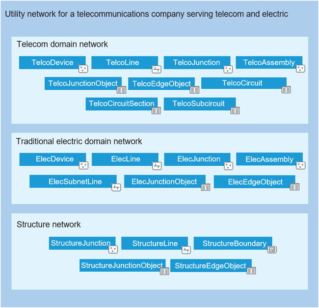
The following diagram shows the classes in a utility network for a telecommunications company that uses a telecom domain network alongside a traditional electric domain network to serve its customers:
Domain network class naming
Each class name is prefixed with the name you provided for the telecom domain network. Additionally, an alias name can be defined when creating a domain network that is applied to each domain network class. For example, a TelcoDevice feature class could have a default alias name of Telco device. The classes included in a telecom domain network are listed in the following table.
The following table includes example names and aliases for classes in a telecom domain network named Telco:
Class names in a telecom domain network
|
Class suffix name |
Class name |
Class alias |
|---|---|---|
|
|
TelcoDevice |
Telco Device |
|
|
TelcoLine |
Telco Line |
|
|
TelcoAssembly |
Telco Assembly |
|
|
TelcoJunction |
Telco Junction |
|
|
TelcoEdgeObject |
Telco Edge Object |
|
|
TelcoJunctionObject |
Telco Junction Object |
|
|
TelcoCircuit |
Telco Circuit |
|
|
TelcoCircuitSection |
Telco Circuit Section |
|
|
TelcoSubcircuit |
Telco Subcircuits |
Telecom domain network attributes
Many of the components and equipment in the telecom industry are represented as nonspatial objects. Modeling these fiber systems can pose unique challenges from a data volume perspective. To address these challenges and decrease the number of records used to store network features in a telecom domain network, associations on domain network classes are modeled using foreign-key fields instead of through the Associations table in the following scenarios:
Junction-edge connectivity associations—Foreign keys are used to establish junction-edge from and junction-edge to connectivity on either side of an edge object using the following fields:
FromSourceID,FromGlobalID,FromFirstUnit,FromLastUnit,ToSourceID,ToGlobalID,ToFirstUnit,ToLastUnit.Containment associations—Foreign keys are used to model containment associations using the
ContainerSourceIDandContainerGlobalIDfields on all domain network classes.Note:
Foreign key-based storage cannot represent multiple containers for a feature. When adding containment associations for lines or edge objects, if the feature already has a container, the content features are added to the Associations table, the
ContainerSourceIDfield is updated with a sentinel value ofAssociation, and theContainerGlobalIDfield isNULL.
All classes in a telecom domain network share the following attributes:
|
Field name |
Field alias |
Description |
|---|---|---|
|
|
Asset group |
Subtype field with the major classification of feature types. |
|
|
Asset type |
Field with minor classifications implemented as attribute domains for each asset group type. |
|
|
Association status |
Describes the type of association in which a feature participates, the role it plays in the relationship, and visibility properties for content features. For more information, see Associations and Association status attribute. |
|
|
Conflict container state |
Used by conflict containers to represent whether content of the feature has changed since the last reconcile operation. |
|
|
Partition ID |
The partition ID for the feature. This field is not currently used and is included to support future enhancements to tracing and network management. |
Note:
Additional fields are added when Global IDs and editor tracking are enabled.
Features from the Device and Junction classes have the following additional attributes:
|
Field name |
Field alias |
Description |
|---|---|---|
|
|
Container source ID |
The source ID of the container that the feature is content of. This is a foreign key attribute used to model containment associations. |
|
|
Container global ID |
The global ID of the container that the feature is content of. This is a foreign key attribute used to model containment associations. |
Features from the Device class have the following additional attribute:
|
Field name |
Field alias |
Description |
|---|---|---|
|
|
Next unit ID |
When the device is configured as a unit container, this sequence is used to assign the next unit identifier value to the grouped unit identifiable object in the feature's containment hierarchy. |
Features from the Assembly class have the following additional attributes:
|
Field name |
Field alias |
Description |
|---|---|---|
|
|
Container source ID |
The source ID of the container that the feature is content of. This is a foreign key attribute used to model containment associations. |
|
|
Container global ID |
The global ID of the container that the feature is content of. This is a foreign key attribute used to model containment associations. |
Features from the Line class have the following additional attributes:
|
Field name |
Field alias |
Description |
|---|---|---|
|
|
Flow direction |
Indicates whether resources flow with or against the digitized direction of a line or if flow is indeterminate when modeling flow using the digitized direction of lines. To learn more, see Flow direction in a utility network. Note:Utility Network Version 7 and later |
|
|
Container source ID |
The source ID of the container that the feature is content of. This is a foreign key attribute used to model containment associations. |
|
|
Container global ID |
The global ID of the container that the feature is content of. This is a foreign key attribute used to model containment associations. |
|
|
Max content unit ID |
The highest unit identifier value allowed for content of the feature. Applicable only to asset types assigned the Edge Unit Container network category. |
|
|
Color scheme |
Indicates the color scheme used for the line feature. The default is |
The JunctionObject table has the following additional attributes:
|
Field name |
Field alias |
Description |
|---|---|---|
|
|
Container source ID |
The source ID of the container that the object is content of. This is a foreign key attribute used to model containment associations. |
|
|
Container global ID |
The global ID of the container that the object is content of. This is a foreign key attribute used to model containment associations. |
|
|
First unit |
First unit of the contiguous group. This is used to identify the first unit in the group (or range) of units that are represented by the object. |
|
|
Last unit |
Last unit in the contiguous group. This is used to identify the last unit in the group (or range) of units that are represented by the object. This is used for validation to ensure the total number of units from the contained objects do not exceed the capacity of the container, and to establish connectivity. |
|
|
Next unit ID |
When the object is configured as a unit container, this sequence is used to assign the next unit identifier value to the grouped unit identifiable object in the junction object's containment hierarchy. |
|
|
Wavelength scheme |
Indicates the wavelength scheme assigned to the junction object. Wavelength schemes are used to define the supported wavelengths for a set of features in a telecom domain network (E.g. for either CWDM or DWDM). |
|
|
Wavelengths |
Indicates the wavelengths value assigned to the junction object. |
The EdgeObject table has the following additional attributes:
|
Field name |
Field alias |
Description |
|---|---|---|
|
|
Flow direction |
Indicates whether resources flow with or against the digitized direction of a line, or if flow is indeterminate when modeling flow using the digitized direction of lines. To learn more, see Flow direction in a utility network. Note:Utility Network Version 7 and later |
|
|
Container source ID |
The source ID of the container that the object is content of. This is a foreign key attribute used to model containment associations. |
|
|
Container global ID |
The global ID of the container that the object is content of. This is a foreign key attribute used to model containment associations. |
|
|
From source ID |
Source ID of the connected junction object on the From side. This is a foreign key attribute used to model connectivity associations. |
|
|
From global ID |
Global ID of the connected junction object on the From side. This is a foreign key attribute used to model connectivity associations. |
|
|
From first unit |
First unit ID of the From side grouping. This is a foreign key attribute used to model connectivity associations. |
|
|
From last unit |
Last unit ID of the From side grouping. This is a foreign key attribute used to model connectivity associations and is used along with the |
|
|
To source ID |
Source ID of the connected junction object on the To side. This is a foreign key attribute used to model connectivity associations. |
|
|
To global ID |
Global ID of the connected junction object on the To side. This is a foreign key attribute used to model connectivity associations. |
|
|
To first unit |
First unit ID of the To side grouping. This is a foreign key attribute used to model connectivity associations. |
|
|
To last unit |
Last unit ID of the To side grouping. This is a foreign key attribute used to model connectivity associations and is used along with the |
|
|
First unit |
First unit of the contiguous group. This is used to identify the first unit in the group (or range) of units that are represented by the edge object (the equipment unit ID) |
|
|
Last unit |
Last unit of the contiguous group. This is used to identify the last unit in the group (or range) of units that are represented by the edge object (the equipment unit ID). This is used along with the |
|
|
Next unit ID |
When the object is configured as a unit container this sequence is used to assign the next unit identifier value to the grouped unit identifiable object in the edge object's containment hierarchy. |
|
|
Max content unit ID |
The highest unit identifier value allowed for content of the object. Applicable only to asset types assigned the Edge Unit Container network category. |
|
|
Record type |
The type of group that this edge object represents (for example, Ungrouped/Cable/Connection). This attribute allows for the correct interpretation of the grouping attributes on the object. The default is |
|
|
Color scheme |
Indicates the color scheme used for the edge object. The default is |
|
|
Wavelength scheme |
Indicates the wavelength scheme assigned to the edge object. Wavelength schemes are used to define the supported wavelengths for a set of features in a telecom domain network (E.g. for CWDM or DWDM). |
|
|
Wavelengths |
Indicates the wavelengths value assigned to the edge object. |
The three circuit management tables created with the first telecom domain network (Circuit, CircuitSection, and Subcircuit) have unique schema and characteristics. To learn more, see Circuit management tables.