Circuit management tables
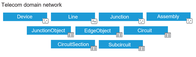
Every domain network consists of a set of feature classes and tables with a fixed schema. When you use the Add Telecom Domain Network tool to create the telecom domain network, three additional tables (Circuit, CircuitSection, and Subcircuit) are created to support circuit management in the network. These system-maintained tables are read-only; however, user-defined attribute fields can be added for attribution.
The Circuit table stores information about the circuits in a telecom domain network. Each row represents a circuit and contains information about the sections that define it, when present.
The CircuitSection table stores information about the sections which define the circuits. Sections represent a collection of elements obtained through a single trace. A section can have multiple records in the table where each row represents a location (starting point, stopping point, or subcircuit) used in the section. Each section in the table must have one or more starting and stopping locations.
The Subcircuit table stores information about circuit subdivisions (subcircuits) which share the capacity or bandwidth of a circuit.
Information in the circuit management tables is updated when importing circuit definitions, when a circuit is verified, when the topology is enabled or validated, and when changes are made to a circuit. As with the other classes in a utility network, the circuit management tables are editor tracking enabled, and when working in an enterprise deployment, they are also branch versioned.
User-defined attribute fields can be added to the circuit management tables to store additional information about a circuit, such as capacity or ownership. These fields are editable through the the Create Circuit and Modify Circuit panes and can be configured to mark a circuit as dirty when modified using the Set Circuit Properties tool.
The circuit management tables are added to the map with the utility network layer and are also listed in the Contents pane for the active map.
Note:
Circuit management tables are included in the schema for utility networks that contain a telecom domain network only.
Circuit table
The Circuit table stores information about the following:
The name of a circuit.
The circuit status (Clean, Dirty, Invalid, or Deleted).
The last time information about a circuit was verified or exported.
When no sections are present (nonsectioned circuits), the starting and stopping locations that define the circuit are modeled using a single record.
When sections are present, information about section ordering that defines the logical connectivity between sections in a circuit.
The Circuit table has the following attributes:
|
Field name |
Field alias |
Description |
|---|---|---|
|
|
Object ID |
The object ID for the record in the table. |
|
|
Name |
The name of the circuit. |
|
|
Section order |
Stores the logical connectivity graph between sections from the CircuitSection table as a JSON string. For example, with a circuit consisting of three sections (1, 2, and 3), if section 1 is connected to section 2, and section 2 is connected to section 3, the section order would be represented as {“1”:[2],“2”:[3],“3”:[]}. When no connection exists between sections, all sections of the circuit are interpreted as being arranged in parallel with the |
|
|
Status |
Specifies whether the circuit is Clean, Dirty, Invalid, or Deleted. The Verify Circuits tool can be used to verify Dirty circuits and mark them as Clean. When errors are encountered during verify, the circuit is marked as |
|
|
Last verified |
The last time the circuit in the table was verified using the verify operation or the Verify Circuits tool. |
|
|
Last exported |
The last time the circuit in the table was exported with acknowledgement using the Export Circuits tool. |
|
|
Start location source ID |
The source ID of the feature or object that is associated with the starting point for the circuit. This is used when modeling a nonsectioned circuit with a single starting and stopping point. This is set to |
|
|
Start location ID |
The global ID of the feature or object that is associated with the starting point for the circuit. This is used when modeling a nonsectioned circuit with a single starting and stopping point. This is NULL when |
|
|
Start location first unit |
The first unit of the group associated with the starting point (for example, equipment unit ID). This is used when modeling a nonsectioned circuit with a single starting and stopping point. This is NULL when |
|
|
Start location last unit |
The last unit of the group associated with the starting point. This is used with the |
|
|
Stop location source ID |
The source ID of the feature or object that is associated with the stopping point for the circuit. This is used when modeling a nonsectioned circuit with a single starting and stopping point. This is NULL when |
|
|
Stop location ID |
The global ID of the feature or object that is associated with the stopping point for the circuit. This is used when modeling a nonsectioned circuit with a single starting and stopping point. This is NULL when |
|
|
Stop location first unit |
The first unit of the group associated with the stop location for the circuit (for example, equipment unit ID). This is used when modeling a nonsectioned circuit with a single starting and stopping point. This is NULL when |
|
|
Stop location last unit |
The last unit of the group associated with the stop location for the circuit. This is used with the |
|
|
Is sectioned |
Specifies whether the circuit is modeled with or without sections. The default is |
|
|
Circuit type |
Specifies whether the circuit is a physical circuit or a virtual circuit. A circuit is considered virtual when it contains one or more sections in which the |
|
|
Error message |
Specifies the error returned by the verify operation when a circuit fails to verify and is marked with a |
|
|
Conflict container state |
Specifies whether the circuit or its related sections or subcircuits have changed since the last reconcile operation. All circuits are conflict containers. |
|
|
Upper name |
The upper case name of the circuit. |
|
|
Global ID |
The global ID of the row in the table. This value is referenced by the CircuitSection table as the |
CircuitSection table
The CircuitSection table stores information about the following:
The information that composes a section in a circuit.
The relationship with the circuit in which the section record participates.
Information about the features or objects that define the section record.
The CircuitSection table has the following attributes:
|
Field name |
Field alias |
Description |
|---|---|---|
|
|
Object ID |
The object ID for the record in the table. |
|
|
Circuit ID |
The global ID of the circuit in which the section participates. Tip:The CircuitSection table can be ordered by the |
|
|
Section ID |
The ID for the section in the circuit. |
|
|
Start location source ID |
The source ID of the feature or object that is associated with the starting point for the circuit section. When the circuit section is associated with a subcircuit, this references the Subcircuit table alias. The default is |
|
|
Start location ID |
The global ID of the feature or object that is associated with the starting point for the circuit section. When the circuit section is associated with a subcircuit, this references the |
|
|
Start location first unit |
The first unit of the group associated with the start location (for example, equipment unit ID) in the circuit section. When the circuit section is associated with a subcircuit, the value is NULL. The default is |
|
|
Start location last unit |
The last unit of the group associated with the start location for the circuit section. This is used with the |
|
|
Stop location source ID |
The source ID of the feature or object that is associated with the stopping point for the circuit section. When the circuit section is associated with a subcircuit, the value is NULL. The default is |
|
|
Stop location ID |
The global ID of the feature or object that is associated with the stopping point for the circuit section. When the circuit section is associated with a subcircuit, the value is NULL. The default is |
|
|
Stop location first unit |
The first unit of the group associated with the stop location (for example, equipment unit ID) in the circuit section. When the circuit section is associated with a subcircuit, the value is NULL. The default is |
|
|
Stop location last unit |
The last unit of the group associated with the stop location for the circuit section. This is used with the |
|
|
Role |
Specifies the role of the record in the circuit. This is used to identify the start, end, and midspan sections of a circuit. This system-maintained field is derived from the
|
|
|
Section type |
Specifies whether the circuit section is physical or virtual. The default is |
|
|
Global ID |
The global ID of the row in the table. |
Subcircuit table
The Subcircuit table stores information about the following:
The name of the subcircuit.
The name of the provider circuit from which the subcircuit originates.
The name of the circuit which consumes the subcircuit.
The Subcircuit table has the following attributes:
|
Field name |
Field alias |
Description |
|---|---|---|
|
|
Object ID |
The object ID for the record in the table. |
|
|
Name |
The name of the subcircuit. |
|
|
Provider ID |
The global ID of the circuit in the Circuit table from which the subcircuit originates. |
|
|
Consumer ID |
The global ID of the circuit in the Circuit table that consumes the subcircuit. |
|
|
Upper name |
The upper case name of the subcircuit. |
|
|
Global ID |
The global ID of the row in the table. |