Work with unit identifiers
A unit identifier, unit ID, or unit, is a label used to identify and distinguish individual components — such as ports, slots, or strands — contained within a single piece of equipment. Unit identifiers apply to all components within a piece of equipment. For junction unit containers, each unit identifier is unique for the equipment in which it is contained. Edge unit containers, however, allow duplicate unit identifiers to support scenarios such as midspan splicing. Unit identifiers are managed at the top of an equipment's containment hierarchy, which logically groups assets in a nonspatial junction object when its asset type is assigned the Unit Identifiable network category.
Despite the name, a unit identifier is not a globally unique ID that references a specific record in the database. Instead, they act as a local abstraction, providing a way to differentiate one component from another within the context of the equipment in which it is contained. For example, Port 1 and Port 2 on a given switch are distinguished by their unit identifiers (unit ID 1 and 2 respectively), but these same labels can appear on any other switch in the network without conflict.
These identifiers are used along with color schemes to differentiate grouped objects that share a set of attributes (such as ports on a card or fibers in a cable) to model connectivity for each individual port or fiber strand.
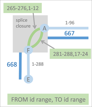
The example above illustrates how unit identifiers can be used to define connectivity between nonspatial edge and junction objects in a circuit. The two connectivity associations displayed using green lines, are used to model the connectivity between junction objects A and F. The top connectivity association connects units 265–276 on the FROM side of junction object F to units 1–12 on the TO side of junction object A in the association. The connectivity association below it models connectivity between units 281–288 on the FROM side of junction object F to units 17–24 on the TO side of junction object A in the association. Connectivity is established between ranges of units on objects using the Modify Associations pane and exposed in the Trace pane to allow you to specify the range of units on which the starting point, stopping point, or barrier should apply when you run a Path or Connected trace.
Three network categories support working with unit identifiers: Junction Unit Container, Edge Unit Container, and Unit Identifiable. Features assigned the Junction Unit Container or Edge Unit Container category act as unit containers, controlling the unit assignment of Unit Identifiable features within their containment hierarchy.
Device features and junction objects can be assigned the Junction Unit Container category, while lines and edge objects can be assigned the Edge Unit Container category. Edge Unit Container features use the Max Content Unit ID field to constrain the number of units within their containment hierarchy.
When a telecom domain network is created, a Next unit ID attribute field is added to the Device, Edge Object, and Junction Object classes. Features assigned either unit container category use this field to control the assignment of unit IDs to objects with the Unit Identifiable category within their containment hierarchy. When a junction object with the Unit Identifiable category is created as content of a unit container, it receives a unit ID based on the NEXTUNITID sequence value on the container, which is updated whenever unit IDs are modified through edits or by reserving unit IDs.
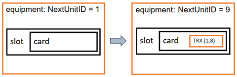
To illustrate, consider a scenario where you create a new piece of equipment with the TelcoDevice asset type to which you have assigned the Junction Unit Container network category. This updates the Next unit ID attribute with a sequence starting at 1. Next, you create a slot and card, followed by a transceiver (TRX) with 8 ports using a junction object asset type (to which you have previously assigned the Unit Identifiable network category) to finalize the containment hierarchy. The transceiver is assigned sequence IDs from the unit container to start from unit 1 with a last unit of 8, updating the First unit attribute value on the object to 1 and the Last unit attribute value to 8. Following this, the Next unit ID attribute value on the equipment would increment to 9.
Multiple unit identifiable features can participate in the containment hierarchy of a feature with multiple unit container features. When multiple unit containers exist in the containment hierarchy of a unit identifiable feature, an upward traversal from the unit identifier is used to locate the first unit container in the object's containment hierarchy to manage unit identifiers for the object.
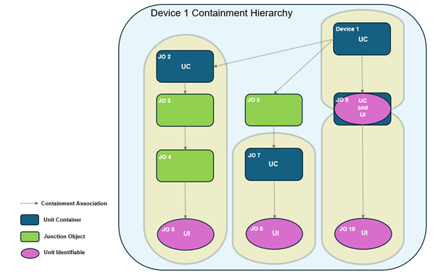
To illustrate, the diagram above displays all features that are content of Telco Device 1 and participate in its containment hierarchy. While multiple unit identifiable features are present as content of Telco Device 1, this unit container device only manages the unit identifiers for JO9. This is because there is content of Device 1 that has also been assigned the Junction Unit Container category. One particular junction object (JO9) is notable in that it is assigned both the Junction Unit Container and Unit Identifiable categories, with its unit identifiers managed by the Next unit ID attribute value on Device 1 while also managing the unit identifiers for JO10. In this scenario, JO2, JO7, and JO9 manage the unit identifiers for JO5, JO8, and JO10 respectively.
Manage unit identifiers with the Unit ID Operations pane
Unit IDs are used in multiple workflows, which include the creation of equipment hierarchies containing unit identifiable features, the establishment of connectivity between objects using the Modify Associations pane or when enabling the network topology, and when specifying the range of unit identifiers to be used for the starting point, stopping point, or barriers in the Trace pane. This section provides an overview of how you can manage unit identifiers on features in your telecom domain network using the Unit ID Operations pane.
The Unit ID Operations pane provides four operations that can be run against unit container and unit identifiable features in a telecom domain network to manage unit identifiers:
Query
Reserve Unit IDs
Reset Unit IDs
Resize Unit IDs
The Query, Reserve Unit IDs, and Reset Unit IDs operations are supported against a selected unit container feature while the Resize Unit IDs operation works with a selected unit identifiable feature.
Requirements
The following requirements must be met to work with unit identifiers in the Unit ID Operations pane:
The Active Item must be assigned the unit container or unit identifiable category and reference a feature from a telecom domain network.
The network topology must be enabled.
Query unit identifiers in a piece of equipment
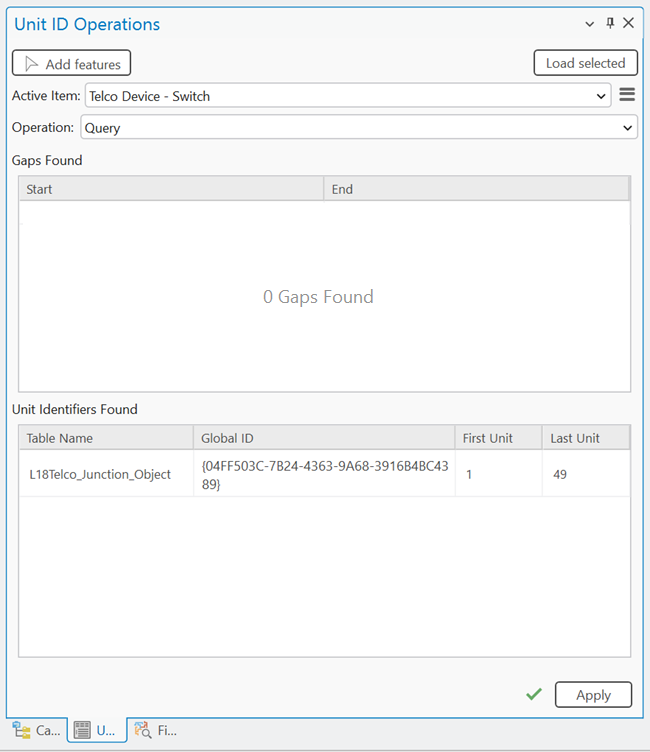
The Query operation returns the units for the selected unit container feature and provides information on whether any gaps are present in the containment units. Over a period of time, gaps in the unit ID space can be introduced through the regular replacement of cards and ports on a piece of equipment. In scenarios in which a strict ordering of unit IDs to port slots is required, the Query operation can be helpful identifying these gaps so that they can be addressed.
To use the Query operation on the pane, complete the following steps:
With a utility network in an active map, click the Utility Network tab on the ribbon.
The Utility Network tab is activated.
On the tab, in the Telecom Circuits group, click Manage Unit IDs.
The Unit ID Operations pane appears with the Add features tool active.
On the map, select a feature with an asset type assigned the Junction Unit Container or Edge Unit Container network category.
For spatial features in the device class, use the Add features tool to select the feature on the map.
For nonspatial junction or edge objects, use the Add selected tool to populate the Active Item with selected rows from the attribute table.
When the Active Item is populated, the Query, Reserve Unit IDs, and Reset Unit IDs options are available from the Operation drop-down menu.
Click the Query operation from the drop-down menu and click Apply.
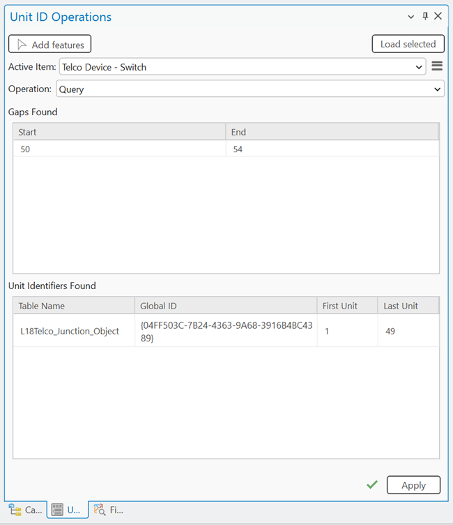
The unit container feature is queried, and any contained unit identifier features are returned. The Gaps Found section displays any gaps identified in the unit identifier space while the Unit Identifiers Found section displays the unit identifiers managed by the unit container feature. You can right-click the unit identifiable features returned in the pane and click Select ![]() to select them in the attribute table, or copy the global ID for use elsewhere.
to select them in the attribute table, or copy the global ID for use elsewhere.
Reserve Unit IDs in a piece of equipment
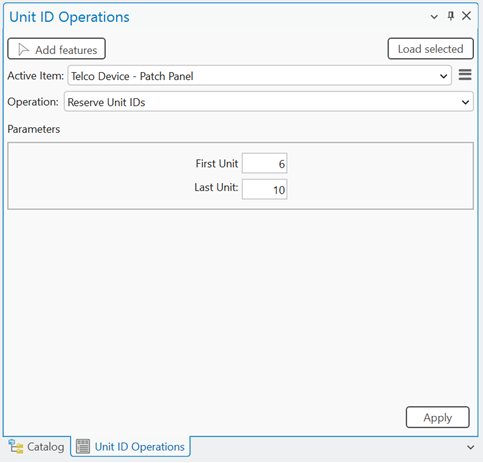
The Reserve Unit IDs operation allows you to create an intentional gap of unit IDs in a unit container feature. Consider a scenario in which you and another editor are working to add cards and ports to a piece of new equipment. If the ports you are to add need to be in positions 11 through 15, but the current Next unit ID sequence value on the unit container feature is 6, the Reserve Unit IDs operation could be used to insert a gap starting at First unit 6 and ending at Last unit 10. Following this operation, the Next unit ID on the container is 11. When you then create the containment associations for the 5 ports they will then be correctly assigned 11 through 15 for their First unit attribute values. The other editor could then use the existing gaps when they perform their work by creating the containment association starting at first unit 6.
To use the Reserve Unit IDs operation on the pane, complete the following steps:
With a utility network in an active map, click the Utility Network tab on the ribbon.
The Utility Network tab is activated.
On the tab, in the Telecom Circuits group, click Manage Unit IDs.
The Unit ID Operations pane appears with the Add features tool active.
On the map, select a feature with an asset type assigned the Junction Unit Container network category.
For spatial features in the device class, use the Add features tool to select the feature on the map.
For nonspatial junction or edge objects, use the Add selected tool to populate the Active Item with selected rows from the attribute table.
When Active Item is populated, the Query, Reserve Unit IDs, and Reset Unit IDs options are available from the Operation drop-down menu.
Click the Reserve Unit IDs operation from the drop-down menu.
For First Unit, provide a value to specify the unit at which the inserted gap will begin.
For Last Unit, provide a value to specify the last unit in the range which to be reserved.
Click Apply.
A gap is inserted into the unit identifier space for the unit container feature and the Next unit ID attribute value on the unit container is updated. If the gap is inserted into an existing identifier space, existing identifiers are extended to begin with the Next unit ID and the From first unit or To first unit values on any edge objects connected to the updated junction objects are updated to maintain connectivity and reference the new unit IDs.
Reset Unit IDs for a piece of equipment
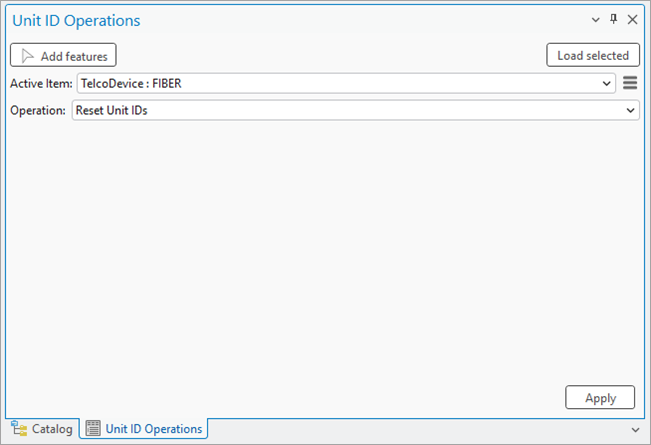
The Reset Unit IDs operation can be used to reset the unit IDs associated with a selected unit container feature. This is done to condense the unit identifier space and remove gaps, or address potential data inconsistency (for example, unit identifiable records out of sync with the unit container) issues.
When run, this operation removes gaps that exist for content of the unit container and resets the Next unit ID attribute value on the container itself. For example, consider a scenario in which gaps are discovered from the Query operation example illustrated in the diagram below.
You can use the Reset Unit IDs operation to remove the existing gap starting at First Unit 50 and ending with Last Unit 54 by shifting the First Unit values down by 5.
Once completed, the Next unit ID attribute value for the Fiber TelcoDevice is updated from 55 to 50 and the From first unit or To first unit values for any edge objects connected to the updated junction objects are reset to maintain connectivity.
To use the Reset Unit IDs operation on the pane, complete the following steps:
With a utility network in an active map, click the Utility Network tab on the ribbon.
The Utility Network tab is activated.
On the tab, in the Telecom Circuits group, click Manage Unit IDs.
The Unit ID Operations pane appears with the Add features tool active.
On the map, select a feature with an asset type assigned the Junction Unit Container network category.
For spatial features in the device class, use the Add features tool to select the feature on the map.
For nonspatial junction or edge objects, use the Add selected tool to populate the Active Item with selected rows from the attribute table.
When the Active Item is populated, the Query, Reserve Unit IDs, and Reset Unit IDs options are available from the Operation drop-down menu.
Click the Reset Unit IDs operation from the drop-down menu.
Click Apply.
The unit identifier space for the selected unit container feature is reset and any existing gaps are removed. The Next unit ID attribute value on the unit container is updated and the From first unit or To first unit values for any edge objects connected to the updated junction objects are reset to maintain connectivity.
Resize the number of units associated with a unit identifier
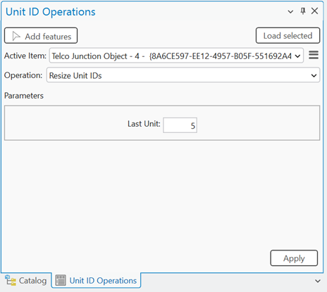
The Resize Unit IDs operation is enabled when an object assigned the Unit Identifiable network category is selected. This operation is used to alter the number of units associated with a unit identifiable feature, either increasing or decreasing the last unit value associated with the object and provides a method to adjust the unit ID information on objects after they are created.
To use the Resize Unit IDs operation in the pane, complete the following steps:
With a utility network in an active map, click the Utility Network tab on the ribbon.
The Utility Network tab is activated.
On the tab, in the Telecom Circuits group, click Manage Unit IDs.
The Unit ID Operations pane appears with the Add features tool active.
On the map, select a feature with an asset type assigned the Junction Unit Container network category.
For spatial features in the device class, use the Add features tool to select the feature on the map.
For nonspatial junction or edge objects, use the Add selected tool to populate the Active Item with selected rows from the attribute table.
When Active Item is populated, the Resize Unit IDs option is displayed in the Operation drop-down menu.
Click the Resize Unit IDs operation from the drop-down menu.
For Last Unit, specify the value to increase or decrease the last unit value assigned to the selected unit identifiable feature.
Click Apply.
The number of units associated with the unit identifiable feature is increased or decreased and the Last unit attribute value on the object is updated. The Next unit ID attribute value on the unit container feature is updated to reflect the change.