Network diagram building
Phases
Generating diagrams is an iterative process that depends on the type of the network inputs from which it starts.
Starting from input network features or network objects, or from network trace locations, this process chains three different phases: the elementary build phase, the diagram rules phase, and the diagram automatic layouts phase.
When working with a telecom domain network with defined circuits, the diagram building can also start from a circuit name provided as an input. For this specific use-case, the process is different. The elementary build phase is ignored and the diagram rules phase is waiting for certain settings without which it cannot properly complete. The diagram automatic layouts phase is identical to that of the other diagrams.
Learn more about diagrams from circuit names and their specifics
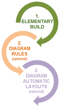
Phase 1—Elementary build
During the elementary build phase of the process, the system creates a diagram feature for each network feature or network object in the input selection set or for each network feature or network object currently specified as starting points among the input trace locations.
Note:
Diagram creation from input trace locations starts with ArcGIS Pro 3.5 | ArcGIS Enterprise 11.5.
Phase 2—Diagram rules
The diagram rules phase occurs when diagram rules are configured on the diagram template. These rules are used to add extra features or objects (for example, trace rule, expand containers rule, add connectivity associations rule), simplify diagram content by aggregating network elements (for example, reduce rules or collapse rules) or by discarding certain network elements (for example, remove rules), and so on. The configured rules are chained, each in turn, in the entry sequence order they were configured in the template. Each rule works on the current diagram content that is built when it enters into action. This means that rule 1 runs on the diagram features built at the end of the elementary build phase, and rule N runs on the diagram features resulting from the (N-1) rule process.
Phase 3—Diagram automatic layouts
The diagram automatic layouts phase is optional. It occurs when diagram layouts are configured on the diagram template to be automatically run during diagram generation. In this case, the configured layouts are chained, each in turn, in the entry sequence order they were configured in the template; that is, layout 1 running on the initial geometry of the features in the diagram, and layout N working from the diagram features geometry resulting from the (N-1) algorithm process.
Sample diagram created from input network features or network objects
The three building phases are as follows:
The diagram building process first creates a diagram feature for each network feature or network object in the input selection set.
It applies rules that are configured on the diagram template to reduce most of the noncritical intervening elements and keep only the critical infrastructure of the network in the diagram.
Since this sample diagram template was also configured to run an automatic Smart Tree layout during the generation, it applies this algorithm.
At the end of the building process, the resulting diagram shows only the remaining critical network elements: those being hierarchically arranged and the distance between them being normalized.
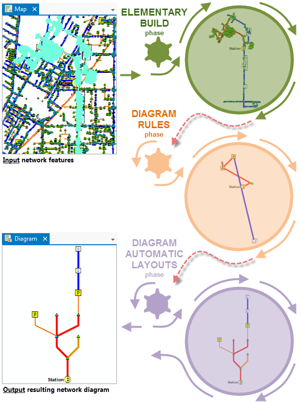
Diagram building specifics
By default, each time the network diagram building process creates a feature in the diagram, it maintains graph completeness and highlights relations between contents and containers.
Completeness of diagram edges
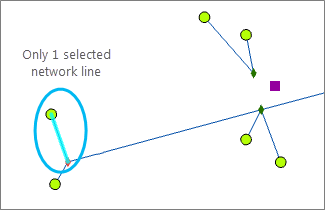
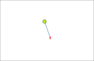
The network diagram building process always ensures completeness of diagram edges during the elementary build and diagram rules phases.
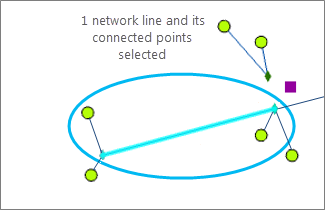
This means that any line feature or edge object—present among the initial input selection set or specified as starting point locations, or added by a rule at a time during the building process—always includes its origin and extremity junctions in the generated diagram, whether those end junctions are part of the input selection or starting locations, or explicitly added by any rule.
|
|
|
Content-container relations
The building process systematically adds containers related to any content features or objects it creates in a network diagram during both the elementary build and diagram rules phases. This means the following are true:
Any content feature or object related to a point container in the network is automatically added to the diagram with its container. This container is represented as a polygon feature, which is drawn around all of the container contents present in the diagram.
Network features are used as input to generate diagram 2. 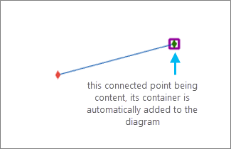
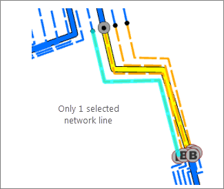
Diagram 2 is built from the input network features. Any content feature or object related to a linear container in the network is automatically added to the diagram with its linear container.
Network features are used as input to generate diagram 3. 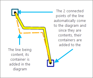
Diagram 3 is built from the input network features.
Caution:
The reverse is false: when a container exists in the diagram, it does not include its contents by default.