Trace Proximity Events (GeoAnalytics Server Tools)
Summary
Traces events that are near each other in space (location) and time. The time-enabled point data must include features that represent an instant in time.
Legacy:
The ArcGIS GeoAnalytics Server extension is being deprecated in ArcGIS Enterprise. The final release of GeoAnalytics Server was included with ArcGIS Enterprise 11.3. This geoprocessing tool is available through ArcGIS Enterprise 11.3 and earlier versions.
Illustration
Usage
The following are examples of use cases that can be performed with the Trace Proximity Events tool:
An organization monitors company-issued devices carried by workers. The company wants to determine which employees were near an individual known to have coronavirus disease 2019 (COVID-19). Using the point layer representing device locations and time, they identify devices that have been within 6 meters and 5 minutes of the contagious person and other possibly contagious employees.
An NGO is monitoring salmon populations using GPS and wants to track the spread of salmon lice between escaped farmed salmon and wild populations. Some GPS-tagged farmed salmon are tracked to determine if they come in close proximity with tagged wild populations, and how those wild populations may further spread the disease. The measurements also include a depth field, which the NGO uses to find fish at a similar depth.
The following terminology is used in the Trace Proximity Events tool:
Entity—An object that has its position periodically recorded, for example, an animal, person, or vehicle. An entity can be stationary or moving.
Entities of interest—The specific entities used to start a trace, for example, a person infected with COVID-19.
Proximity event—The period of time when two entities are near each other, for example, two people that come within 3 meters of each other and within a 1-minute window of each other.
Depth—The degree of separation between an entity of interest and an entity farther down the trace (downstream). For example, a proximity event between the entity of interest and someone else is depth 1.
Trace event—The first contact for a specified entity downstream from the entities of interest.
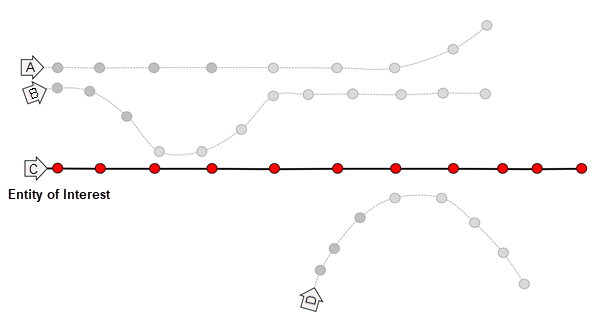
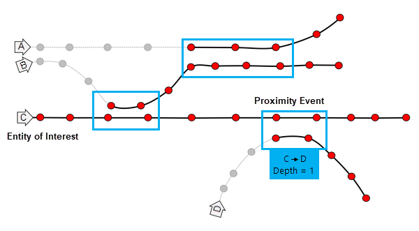
The diagrams below show how the Trace Proximity Events tool processes data. In these diagrams, time is on the x-axis.
In each diagram, there are four entities: A, B, C, and D. The highlighted text describes the trace events that occur between two entities (the from and to entities) and the depth of the proximity event. In this example, entity C is the entity of interest that is being traced downstream.
In diagram 1, entity C is the chosen entity of interest. The depth is 0.
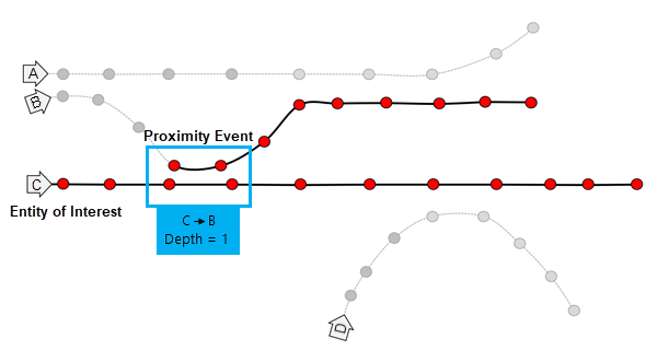
In diagram 2, a proximity event occurs between entities C and B. The depth of the trace is 1. When multiple features are subsequent proximity events, this is a sustained proximity event.
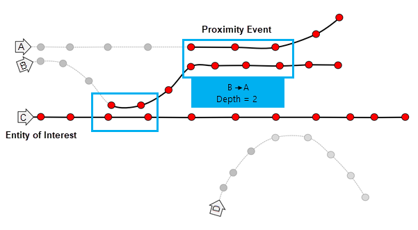
In diagram 3, a proximity event occurs between entities B and A. The depth of the trace is 2.
In diagram 4, a proximity event occurs between entities C and D. The depth of the trace is 1.
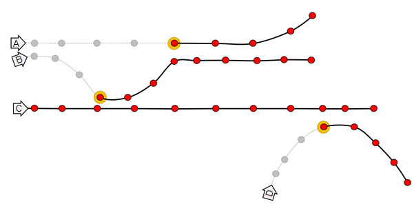
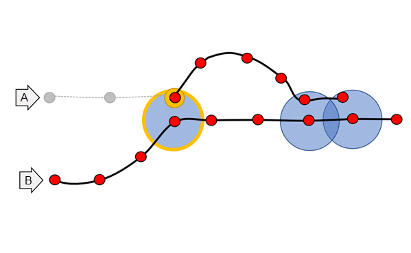
In the image below, entity B is the entity of interest and comes in proximity with entity A three times, denoted by the blue circles. Assuming that time is on the x-axis, the first proximity event is 1, followed by a break without contact; then proximity events 2 and 3 occur. The tool will return event 1 as the trace event. Proximity events 2 and 3 are not returned in the Output Proximity Events parameter layer. All features after proximity event 1 are returned in the Output Tracks parameter.
Features must meet both the Spatial Search Distance and Temporal Search Distance parameter criteria to be considered near each other.
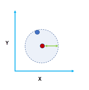
Figure A: The two features are within a spatial search distance of each other. 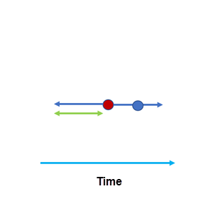
Figure B: The two features are within a time distance (temporal search distance) of each other. Specifying a larger temporal search distance and spatial search distance will result in more events and take longer to process the results. Smaller distances will result in fewer events and a shorter processing time.
Use domain-specific knowledge to determine the values used for the Spatial Search Distance and Temporal Search Distance parameters. Consider factors such as the accuracy of the device when setting the distances.
The Define Entities of Interest Using parameter supports the following options:
Entities of Interest IDs—This option enables the Entities of Interest IDs parameter, which requires Entity ID values and optional Starting From time values to start tracing from.
Selected features in a specified entity of interest layer—This option enables the Entities of Interest Layer parameter, which allows you to choose a layer that includes entity IDs and, optionally, times to start tracing from. For this layer, the entity ID field name must match the entity ID field name from the input layer. Time will be used on this layer if the layer is time enabled.
The entity of interest is where the proximity tracing will begin. If you specify a starting from time, tracing will begin at that time for that entity. If you do not specify a time, tracing will begin on January 1, 1970, for that entity.
You can set additional requirements for a proximity event. For example, you can trace only individuals in a particular building on a campus, or you can trace only within one level of a building. Use the Attribute Match Criteria parameter to specify constraining attributes. For example, to constrain entities on the same floor, specify the
Floorfield.The Output Proximity Events layer will contain the first proximity event for the entities in the trace, as well as the following fields:
from_id—The upstream entity ID.to_id—The downstream entity ID.depth—The degree of separation between the entity of interest and theto_idfield.duration_minutes—The duration of the trace event in minutes. This field is calculated as the difference between the start and end times. For example, 1.5 minutes is 90 seconds. A value of 0 means that there is a single proximity event (same start and end time).instant_datetime—The date and time of the proximity event. This field is calculated as the first recorded time that meets the criteria of the proximity event.
The Output Proximity Events layer can be visualized using the time slider or in a link chart to visualize the trace results.
You can use the optional Output Tracks parameter to create a layer that contains the first trace event and all subsequent features for that entity. These results are helpful for visualizing where entities travelled and can be used in the Reconstruct Tracks tool. The Output Tracks parameter will include the following fields:
entity_id—The entity ID.depth—The degree of separation between the entity of interest and the trace track. The depth will be the same across a single track.date—The date of each feature. This will be the same date as the record from the input features.
Input points that do not have time values, geometry values, or an entity ID field are not included in the results.
When using proximity tracing to find the transmission (such as a disease), consider the following:
The presence of a trace event does not guarantee that it has been transmitted; it is only a potential encounter.
The absence of a trace event does not mean that something hasn't been transmitted. In cases such as a disease, there may be transmission through other vectors.
When possible, use the Attribute Match Criteria parameter to constrain proximity events when required. For example, use attributes to constrain the room, floor, or elevation.
If you want to calculate all proximity events and don't want to trace downstream from an entity of interest, use the Join Features tool.
You can improve performance of the Trace Proximity Events tool by doing one or more of the following:
Use smaller values for the Spatial Search Distance and Temporal Search Distance parameters.
Limit the entities of interest using the Attribute Match Criteria parameter.
Specify a Maximum Trace Depth parameter value to limit the number of downstream traces for a given entity and the entity of interest.
Set the extent environment so that you only analyze data of interest.
Use data that is local to where the analysis is being run.
When running GeoAnalytics Server tools, the analysis is completed on GeoAnalytics Server. For optimal performance, make data available to GeoAnalytics Server through feature layers hosted on your ArcGIS Enterprise portal or through big data file shares. Data that is not local to GeoAnalytics Server will be moved to GeoAnalytics Server before analysis begins. This means that it will take longer to run a tool and, in some cases, moving the data from ArcGIS Pro to GeoAnalytics Server may fail. The threshold for failure depends on your network speeds, as well as the size and complexity of the data. It is recommended that you always share your data or create a big data file share.
Learn more about sharing data to your portal
Learn more about creating a big data file share through Server Manager
Parameters
| Label | Explanation | Data type |
|---|---|---|
|
Input Points |
The time-enabled point feature class that will be used to trace proximity events. |
Feature Set |
|
Entity ID Field |
The text field representing unique IDs for each entity. |
Field |
|
Output Name |
The name of the output feature service. |
String |
|
Distance Method |
Specifies the distance type that will be used with the Spatial Search Distance parameter.
|
String |
|
Spatial Search Distance (Optional) |
The maximum distance between two points to be considered in proximity. Features within the spatial search distance and temporal search distance criteria are considered to be in proximity of each other. |
Linear Unit |
|
Temporal Search Distance (Optional) |
The maximum duration between two points to be considered in proximity. Features within the temporal search distance and that meet the spatial search distance criteria are considered to be in proximity of each other. |
Time Unit |
|
Define Entities of Interest Using |
Specifies the entities of interest.
|
String |
|
Entities of Interest IDs |
The entity names and start times for the entities of interest. This parameter is supported only when Entities of Interest IDs is specified for the Define Entities of Interest Using parameter. Value table columns:
|
Value Table |
|
Entities of Interest Layer |
The layer or table that contains the entities of interest. This parameter is supported only when Selected features in a specified entity of interest layer is specified for the Define Entities of Interest Using parameter. |
Record Set |
|
Output Tracks (Optional) |
Specifies whether an output layer containing the first trace event and all subsequent features for that specified entity will be generated.
|
Boolean |
|
Maximum Trace Depth |
The maximum degrees of separation between an entity of interest and an entity farther down the trace (downstream). |
Long |
|
Attribute Match Criteria (Optional) |
The fields used to constrain the proximity event. |
Field |
|
Data Store (Optional) |
Specifies the ArcGIS Data Store where the output will be stored. All results stored in a spatiotemporal big data store will be stored in WGS84. Results stored in a relational data store will maintain their coordinate system.
|
String |
Derived output
| Label | Explanation | Data type |
|---|---|---|
|
Output Proximity Events |
The layer containing traced proximity events. |
Feature Set |
|
Output Tracks |
The optional layer containing the first trace event in the tracks and all subsequent features. |
Feature Set |
Environments
Output Coordinate System, Extent, Current Workspace
Special cases
- Output Coordinate System
-
The coordinate system that will be used for analysis. Analysis will be completed in the input coordinate system unless specified by this parameter. For GeoAnalytics Tools, final results will be stored in the spatiotemporal data store in WGS84.
Licensing information
- Basic: Requires ArcGIS GeoAnalytics Server
Available with ArcGIS Enterprise 10.9 - Standard: Requires ArcGIS GeoAnalytics Server
Available with ArcGIS Enterprise 10.9 - Advanced: Requires ArcGIS GeoAnalytics Server
Available with ArcGIS Enterprise 10.9