Compute Coherence (Image Analyst Tools)
Summary
Computes the similarity between the reference and secondary input complex radar data.
The output is a coherence raster with a value range of 0 to 1 in which 0 indicates no coherence and 1 indicates perfect coherence. A value of 0.3 or above is considered a good coherence value.
Usage
The inputs must be a pair of coregistered complex radar datasets.
The output coherence raster can be used for coherent change detection. The output coherence raster can be used in InSAR and DInSAR workflows to assess the reliability of the interferogram pixels.
For InSAR and DInSAR applications, the input radar data must have the same satellite geometry.
In the Geoprocessing pane, the Range Window Size and Azimuth Window Size parameters include information about the estimate size required to create an approximate square pixel for the Input Radar Data parameter value.
Baseline considerations for InSAR applications are shown in the following table:
Baseline type
Definition
Smaller baseline
Larger baseline
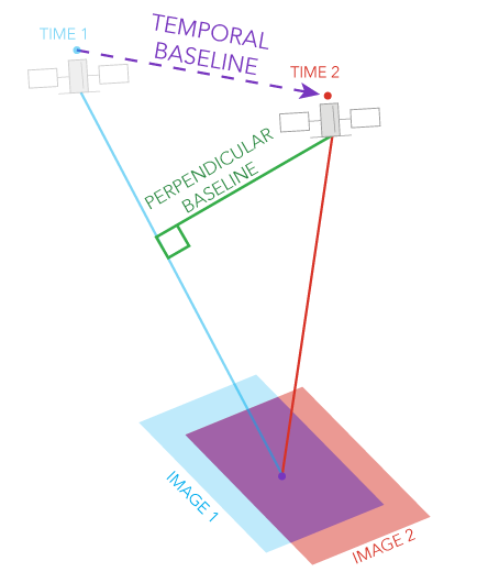
Perpendicular baseline
The component of the physical separation between the two satellite acquisition positions that is perpendicular to the line of sight (LOS).
Preserves phase coherence, which is ideal for surface deformation monitoring. Sensitivity to elevation differences is reduced, making it less ideal for DEM generation.
Increases sensitivity to topography, which is ideal for DEM generation.
Temporal baseline
The time separation between the two acquisitions.
Better coherence in dynamic areas and captures rapid changes such as landslides and earthquakes.
Suitable for detecting slow, cumulative deformation such as tectonic motion, although it carries a risk of decorrelation.
Parameters
| Label | Explanation | Data type |
|---|---|---|
|
Input Reference Radar Data |
The input reference complex radar data. |
Raster Dataset; Raster Layer |
|
Input Secondary Radar Data |
The input secondary complex radar data. |
Raster Dataset; Raster Layer |
|
Output Radar Data |
The output coherence radar data. |
Raster Dataset |
|
Polarization Bands (Optional) |
The polarization bands that will be corrected. The first band is selected by default. |
String |
|
Range Window Size (Optional) |
The range window size in pixels. The default value is 10. |
Long |
|
Azimuth Window Size (Optional) |
The azimuth window size in pixels. The default value is the minimum number of pixels required to create an approximate square window. For example, if the Range Window Size parameter value is 10, the default will be 3. |
Long |
Environments
Cell Alignment, Compression, Current Workspace, NoData, Parallel Processing Factor, Pyramid, Raster Statistics, Resampling Method, Scratch Workspace, Snap Raster, Tile Size
Licensing information
- Basic: Requires Image Analyst
- Standard: Requires Image Analyst
- Advanced: Requires Image Analyst