Generate Floor Plan From Point Cloud (Indoors Tools)
Summary
Creates a polyline feature class containing 2D polyline features generated from input point cloud data. The output of this tool can be refined and used as an input when populating an Indoors workspace with data to assist with creating floor-aware maps and scenes.
Usage
This tool accepts a LAS file as input and creates 2D polyline features that represent vertically-extended architecture such as walls, doors, and columns. Use this tool as part of a larger workflow to generate floor plans from point clouds.
You can refine the output polyline feature class created by the tool for use as input to the Import Features To Indoor Dataset tool.
This tool uses a projected coordinate system when processing the point cloud coordinates and when creating the output line features. When the input point cloud has a coordinate system, the Coordinate System parameter will be set to that coordinate system by default. When the input point cloud does not have a coordinate system, use the Coordinate System parameter to specify a projected (not geographic) coordinate system appropriate for the scan location. A vertical coordinate system is recommended but not required; z-values may be relative to the ground, sea level, or any other reference.
If the input point cloud has an incorrect coordinate system defined, change it from the input point cloud's layer properties.
If the point cloud uses a local coordinate system, use the Move, Rotate, and Scale tools in the Modify Features pane to reposition the generated polylines as needed.
This tool processes one level (floor) from one facility per tool run. If the input point cloud data covers multiple facilities or levels, use the following Processing Boundary parameters to limit the processing area:
Use the Z Ranges parameter to limit processing to a single level or a subset of elevations on a level.
Use the Extent parameter to limit processing to a single facility or a subset of a facility. The Extent parameter takes precedence over the Extent environment.
To improve the quality of the output, use the Z Ranges parameter to limit processing to a range of z-values that excludes most furniture, fixtures, lighting, and other objects that aren't room-bounding features.
Note:
When using this tool with a single z-range, do not specify a Z Ranges parameter value and set the LAS Elevation Range filter instead. This can significantly reduce tool run time.
Explore the point cloud data in a local scene to determine the optimal range of z-values. The following illustration shows how a processing z-range of 1-2 meters can avoid furniture and ceiling fixtures:
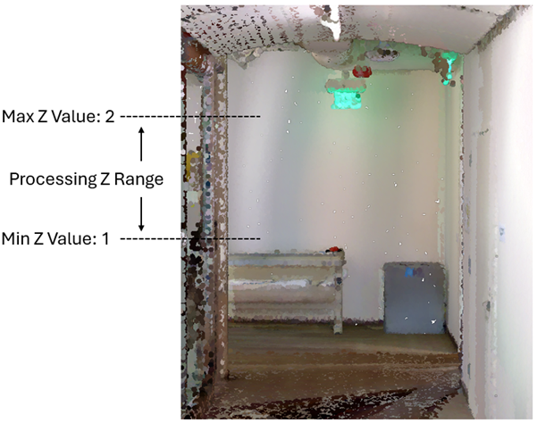
A minimum z-value of 1 and a maximum z-value of 2 are set to avoid capturing furniture and ceiling fixtures in a room. Use the Simplify Lines parameter to consolidate and straighten generated output polylines, close small gaps, and reduce the number of vertices. When this parameter is checked, a polyline compression algorithm is used to normalize generated polylines before removing extra vertices that are not necessary for retaining effective areas, and a computer vision algorithm is used to detect corners for splitting polylines into architectural details.
Use the Short Feature Tolerance parameter to delete short polyline features from the data. Features shorter than or equal to the specified tolerance will be removed unless they are within 0.05 meters (2 inches) of other features. Use a value of zero to avoid short features being removed, which can be helpful for visualizing wall positions in sparse point cloud data.
The optional Output Raster parameter can provide context when editing the output polylines. This parameter supports
.tifand.pngraster file formats, a geodatabase raster, or a raster in the memory workspace.This tool may use the input point cloud's
KeyPointclassification field during processing. If so, the tool will restore the field values to the original values at the end of the tool run.
Parameters
| Label | Explanation | Data type |
|---|---|---|
|
Input Point Cloud |
The input LAS file or dataset containing point cloud data from which polyline features will be generated. |
LAS Dataset Layer |
|
Output Line Features |
The polyline feature class that will be created to store features generated from LAS data. If no workspace is specified, the scratch workspace will be used. |
Feature Class |
|
Coordinate System (Optional) |
The coordinate system of the input LAS data and the output polyline feature class. By default, the coordinate system that is defined in the LAS data for both horizontal and vertical coordinate systems will be used. |
Spatial Reference |
|
Output Z Value (Optional) |
The z-value that will be assigned to the generated polyline features. The default is 0. You can specify a value in meters or feet. The tool will automatically convert the value to use the unit of measure of the vertical coordinate system of the data. |
Linear Unit |
|
Simplify Lines (Optional) |
Specifies whether output polylines will be simplified during processing. This parameter uses a polyline compression algorithm to normalize generated polylines before removing extra vertices that are not necessary for retaining effective areas. This parameter also uses a computer vision algorithm to split polylines at recognizable corners.
|
Boolean |
|
Short Feature Tolerance (Optional) |
The tolerance in meters or international feet that will cause short features to be deleted. The default is 1 meter. Use a value of 0 to bypass the deletion of short features. |
Linear Unit |
|
Z Ranges (Optional) |
One or more z-ranges of the input point cloud. Points in the specified z-ranges will be analyzed when generating the output polyline features. If no value is specified, the full range of z-values present in the input point cloud data will be used. Value table columns:
|
Value Table |
|
Extent (Optional) |
The extent of the data that will be evaluated.
When coordinates are manually provided, the coordinates must be numeric values and in the active map's coordinate system. The map may use different display units than the provided coordinates. Use a negative value sign for south and west coordinates. |
Extent |
|
Output Raster (Optional) |
The output raster that will be generated from the input point cloud data. Supported formats are a geodatabase raster, a raster in the memory workspace, and If no value is provided, the output raster will not be saved and will be deleted after the polylines are generated. |
Raster Dataset |
Environments
Extent, Parallel Processing Factor
Licensing information
- Basic: No
- Standard: No
- Advanced: Requires 3D Analyst and ArcGIS Indoors Pro or ArcGIS Indoors Maps. Also requires Spatial Analyst or Image Analyst