Tutorial: Create digital imagery products with ArcGIS Pro Ortho mapping using Server
![]() Available with Advanced license.
Available with Advanced license.
In ArcGIS Pro, you can photogrammetrically correct digital aerial imagery collected by a professional mapping camera to remove geometric distortions induced by the sensor, viewing geometry, and correct for terrain displacement. After addressing these effects, you can generate Ortho mapping products. This processing can be performed remotely on your self-hosted enterprise infrastructure, enabling you to leverage multi-machine configuration for distributed processing.
In this tutorial, you will set up an Ortho mapping workspace to manage your aerial imagery collection. Next, you will perform a block adjustment and review the results. Finally, you'll generate a digital surface model (DSM) and an orthorectified mosaic, or orthomosaic.
Computing the photogrammetric solution for aerial imagery is determined by its exterior orientation (EO), which represents a transformation from the ground to the camera and its interior orientation (IO), which represents a transformation from camera to image. Required exterior orientation parameters include perspective center (x, y, z), and Omega, Phi, and Kappa, and are provided in an Esri Frames Table. Interior orientation parameters include focal length, pixel size, principal point, and lens distortion. This information can be found in the camera calibration report associated with your imagery and must be provided in an Esri Camera Table.
Note:
ArcGIS Image Server configured for raster analysis or ArcGIS Reality Server is needed to complete this tutorial. To set up an ArcGIS Image Server raster analysis site, please see raster analytics deployment. For Reality Server configuration, please refer to the Reality Server installation.
Connect to Server
To utilize Server for processing your data in ArcGIS Pro, you need to first connect to the Server.
Open ArcGIS Pro, Click the Project tab on the ribbon and click the Portals page.
You can also access the portals page from the Manage Portals link in the Sign In menu
 .
.Click Add Portal.
Enter the URL (
https://webadaptorhost.domain.com/webadaptorname) for the portal on the Add Portal dialog box and click OK.Sign in to the portal by clicking the Options button
 or right-click the portal and click Sign in. Enter your username and password.
To make the new connection your active portal, right-click the URL and click Set As Active Portal.
Once you successfully connect to your portal, your username will show up in the top right corner of ArcGIS Pro.
Create an Ortho mapping workspace
An Ortho mapping workspace is an ArcGIS Pro subproject that is dedicated to Ortho mapping workflows. It is a container in an ArcGIS Pro project folder that stores the resources and derived files that belong to a single image collection in an Ortho mapping task.
A collection of digital aerial images is provided for this tutorial. The tutorial data also contains frame and camera tables.
To create an ortho mapping workspace, complete the following steps:
Download the tutorial dataset, unzip it and save the content to
C:\SampleData\Aerial Imagery.If you save your data to a different location on your machine, make sure to update the path in each of the entries in the Frames Table file.
In ArcGIS Pro, create a project using the Map template.
On the Imagery tab, in the Reality Mapping group, click the New Workspace drop-down menu and choose New Workspace.
In the Workspace Configuration window, type a name for the workspace.
Click the Workspace Type drop-down list, and choose Ortho Mapping.
Ensure that the Sensor Data Type is set to Aerial - Digital.
Click the Basemap drop-down menu, and choose Topographic.
Set the Parallel Processing Factor. This controls the maximum computational resource for distributed processing. It is recommended to use percentage expression. For example, if you have 2 Server nodes, set Parallel Processing Factor to 50% to utilize one machine for block adjustment and ortho mapping product generation.
Check Process this image collection on server.
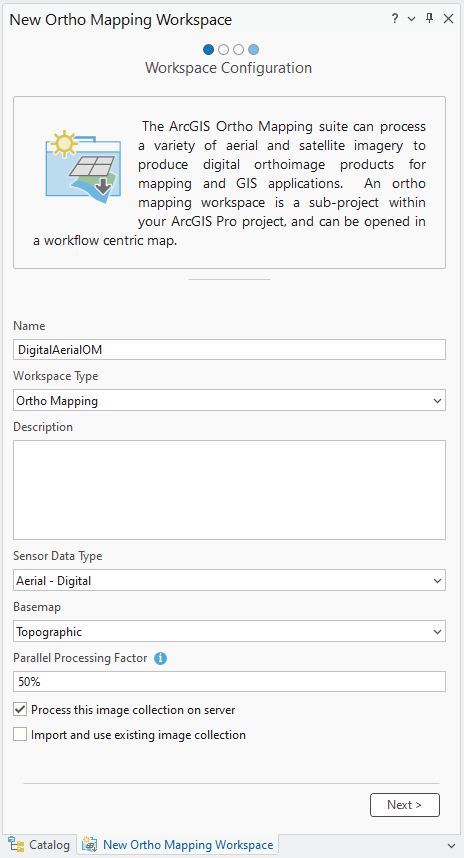
Accept all other default values and click Next.
The Image Collection window appears.
In the Image Collection window, for Sensor Type, ensure that Generic Frame Camera is chosen.
Under Exterior Orientation File / Esri Frames Table, navigate to the tutorial data folder on your machine and select the Frames table file (
FrameTable.csv).This table specifies parameters that are used to compute the exterior orientation (EO) of your imagery. In the block adjustment process, these approximate values are refined to achieve higher accuracy.
Make sure that the data paths listed in the
rastercolumn in the frame table file match the location of the image files on your machine.Under Cameras, click the Import button
 , navigate to the tutorial data folder on your machine, and select the camera table file (
CameraTable).This file contains the interior orientation (IO) for the camera.
For this tutorial, the Esri frame and camera tables have been provided in the proper format. For other data sets, you will likely need to build and format these tables. For more information, see Frame and Camera tables.
Make sure the Spatial Reference and Camera Model are correct.
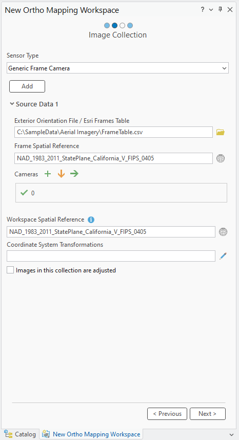
The default projection for the workspace is defined based on your imagery. This projection must match the coordinates used in the frame table, and it determines the spatial reference for your ortho products, including the orthomosaic and DSM. For this dataset, we’ll use the default projection.
Click Next.
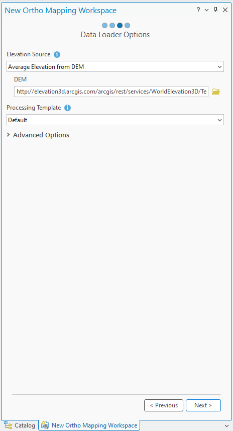
Accept the default settings in the Data Loader window and click Next.
If you have access to the internet, Elevation Source will be derived from the World Elevation Service. If you do not have access to the internet or a DEM, choose the Constant Elevation option from the drop-down menu and enter a representative elevation value.
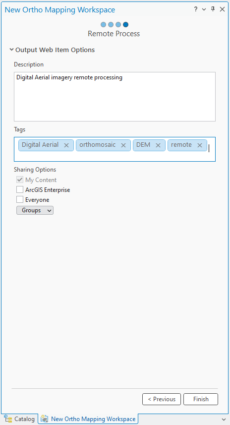
In the Remote Process window, provide description and tags for the image service and click Finish.
Once the workspace has been created, the images are displayed. An Ortho Mapping category is added to the Contents pane, where the image collection image service and derived Ortho mapping products service will be stored.
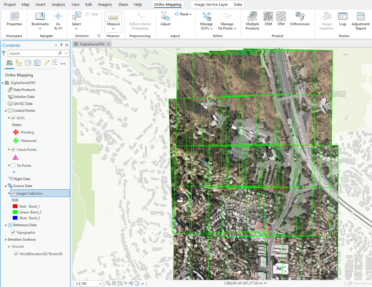
To see the image footprints, you can right click on the Image Collection in the Contents pane > Properties > Display > Check on Display Footprints.
The initial display of imagery in the workspace confirms that all images and necessary metadata were provided to initiate the workspace. The images have not been aligned or adjusted, so the mosaic may not appear geometrically correct. Note: You may need to zoom in close enough to see the image.
A new Ortho Mapping tab will be added to the ArcGIS Pro main menu. Clicking this tab will expose a series of tools and workflows dedicated to Ortho mapping. In the Product category, all the buttons are unavailable because the images are not yet adjusted.
Perform a block adjustment
The next step is to perform block adjustment using the tools in the Adjust and Refine groups. The block adjustment will first calculate tie points, which are common points in areas of image overlap. The tie points will then be used to calculate the orientation of each image, known as "exterior orientation" in photogrammetry.
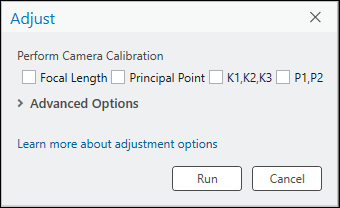
In the Ortho Mapping tab, in the Adjust group, click Adjust
 .
.Ensure the Perform Camera Calibration options are unchecked.
By default, for digital aerial imagery, most airborne sensors have been calibrated, and provide accurate interior orientation values in a camera calibration report. Automatic camera calibration is typically applied to other types of data, like low-cost drone cameras, to compute and improve the camera’s geometric parameters, while simultaneously determining image orientation and image ground coordinates.
Accept all remaining default settings and click Run to perform block adjustment.
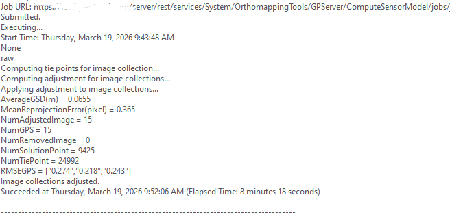
In the Ortho Mapping tab, in the Review group, click Logs
 .
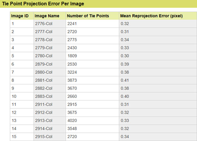
.Tie point residuals or accuracy reporting can be viewed in the logs file. The units for tie point Root-Mean-Square Error (RSME) is pixels.
Review adjustment results
In the Ortho Mapping tab, in the Review group, click Adjustment Report to generate adjustment statistics.
The adjustment report provides a record of the adjustment and overall quality measures of the process.
Generate a digital Surface Model (DSM)
The stereo image pairs of an image collection are used to generate a point cloud (3D points) for which elevation data can be derived. The derived elevation data is classified as either a digital terrain model (DTM), which includes only the ground surface, or a digital surface model (DSM), which includes the elevations of trees, buildings, and other above ground features.
Note:
Elevation values can be derived when the image collection has a good amount of overlap to form the stereo pairs. Typical image overlap necessary to produce point clouds is 80 percent forward overlap along a flight line and 60 percent overlap between flight lines.
Follow the steps below to generate a DSM using the wizard.
On the Ortho Mapping tab, click the DSM button
 in the Product group.
The Ortho Mapping Products Wizard window appears.
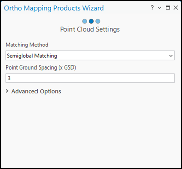
Click Next to advance the wizard to the Point Cloud Settings window.
In the Point Cloud Settings window, for Matching Method, choose Semiglobal Matching from the drop-down menu.
This method is typically used for images of urban areas and captures more detailed terrain information.
Accept the default Point Ground Spacing value.
This defines the spacing, in meters, at which the 3D points are generated. The default is three times the resolution of the source imagery.
Accept all remaining default settings and click Next.
For information on Advanced Settings, see Create elevation data using the ortho mapping DEMs wizard.
In the DSM Settings window, for Cell Size, use the default value of 3 x GSD.
This will determine the resolution of the DSM, which is three times the imagery resolution, in this case.
Accept the remaining default settings and click Finish.
The DSM will be generated.
Generate a orthomosaic
Next, you will generate an orthomosaic. An orthomosaic is an orthorectified image product mosaicked from an image collection. Geometric distortion has been corrected and the imagery has been color balanced to produce a mosaic.
On the Ortho Mapping tab, in the Product group, click Orthomosaic to start the Orthomosaic Wizard.
Ensure Color Balance and Generate Seamlines options are checked.
Click Next.
In the Color Balance Settings pane, for Balance Method, select Dodging from the drop-down list and accept all other default options.
Click Next.
In the Seamline Settings window, for Computation Method, select Radiometry in the drop-down list.
Expand the Processing section, and input 20 for Blend Width.
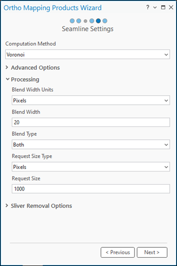
Click Next.
The wizard guided workflow advances to the next pane, Orthomosaic Settings.
Accept all the default settings in the Orthomosaic Settings pane, and click Finish.
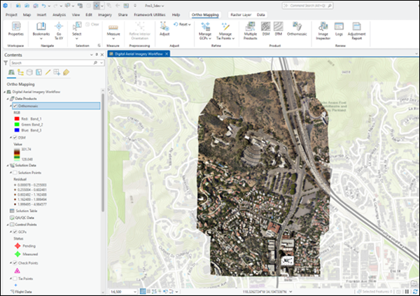
The orthomosaic will be generated, listed in the Contents pane, and loaded into the map display.
Summary
In this tutorial, you connected to Server and created a Ortho mapping workspace for digital aerial imagery and used Adjust tools to perform a photogrammetric adjustment. You then used tools in the Products group to generate DSM and orthomosaic.