Event creation using feature creation
 Available with the Linear Referencing license.
You can digitize an event in a feature service using the feature template for that layer in the Create Features pane  . The tool automatically populates the route ID and measures to associate the event with the route where you create the feature. The Attributes pane appears where you can review existing event attributes and provide additional event attributes.
Before editing a feature service, you must share branch versioned linear referencing system (LRS) data as a web layer. If the feature service is not yet published, see Share as web layers.
Tip:
Click Create Features
on the Edit tab to open the Create Features pane and expand the feature template for the feature service layer.If a message regarding acquiring locks or reconciling appears, it means that conflict prevention is enabled.
When you create a point event, the tool populates the route ID, measure, and date fields based on the underlying route.
When you digitize a line event, the first vertex is used to populate the From Measure, From Date, To Date, and From Route fields, and the last vertex is used to populate the To Measure and To Route fields.
For a line event that spans routes, the start and end measures must be on routes that have the same line ID.
Learn more about creating polyline features
Location errors
If you add the feature outside the tolerance value and the tool cannot detect the route ID or measures, a location error occurs.
Note:
You can also review a complete list of location errors.
Any of the following statuses indicate a problem that should be resolved:
| Location error | Description |
|---|---|
| Different From Route And To Route Line IDs | The starting route and the ending route have different line IDs. This is applicable to events associated with line networks. |
| Invalid Route Line ID | The route's line ID is invalid. This is applicable to events associated with line networks. |
| Invalid Location Route ID | The route location's route ID is invalid (NULL, empty, or invalid value). |
| Invalid Location Measure | At least one of the route location's measure values is invalid. |
| Invalid Route ID | The route location's route ID is invalid (NULL, empty, or invalid value). |
| Measure Extent Out Of Route Measure Range | The route location's shape doesn't exist on the route. The route has no m-values, or the route location's measures don't exist on the route. |
| Multiple Route Locations Found | More than one point location was found. Measures may not be unique along the routes. |
| Null Extent | The start measure is equal to the end measure. |
| Parent Event Not Found | The route location's shape was not found because the start measure and the end measure are outside the route measures. |
| Partial Match For The From Measure and To Measure | The start measure and the end measure are outside the route measure range. |
| Partial Match For The From Measure | The start measure is outside the route measure range. |
| Partial Match For The To Measure | The end measure is outside the route measure range. |
| Reversed Line Order | The starting route does not have a lower line order than the ending route. This is applicable to line networks. |
| Route Location Not Found | The route location's shape doesn't exist on the route. The route has no m-values, or the route location's measures don't exist on the route. |
| Route Not Found | The route does not exist. This may be due to the route not existing in the network or the route and event having different time ranges that do not overlap. |
| Route Shape Empty | The route does not have a shape, or the shape is empty. |
Scenarios for adding a line event using feature creation
In the scenarios below, a line event is added using the feature template in the Create Features pane.
Line event creation
The following diagram shows the route attributes:
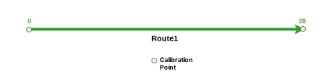
The following table details the route attributes. Route 1 has measures from 0 to 20:
| Route ID | From Date | To Date |
|---|---|---|
| Route1 | 1/1/2000 | <Null> |
The following diagram shows the creation of a line event. The first and last vertices intersect Route 1, which results in a new line event.
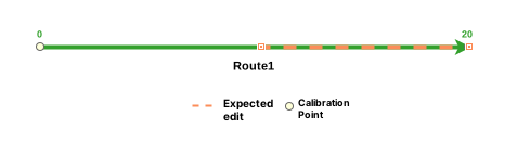
The following table details the line event:
| Event | Route ID | From Date | To Date | From Measure | To Measure | Location Error | MAOP Design |
|---|---|---|---|---|---|---|---|
| Event1 | Route1 | 1/1/2000 | <Null> | 10 | 20 | No Error | 800 |
| Event | Route ID | From Date | To Date | From Measure | To Measure | Location Error | Speed Limit |
|---|---|---|---|---|---|---|---|
| Event1 | Route1 | 1/1/2000 | <Null> | 10 | 20 | No Error | 55 |
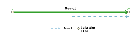
The following diagram shows the route and the associated event after the edit:
Line event creation resulting in a location error
The following diagram shows the route attributes. Route 1 has measures from 0 to 20.
The following table details the route attributes:
| Route ID | From Date | To Date |
|---|---|---|
| Route1 | 1/1/2000 | <Null> |
The following diagram shows the creation of a line event. Only the first vertex intersects Route 1. The route ID and starting measure are populated, but the end measure is <Null> because the last vertex does not intersect the route.

The following table details the line event:
| Event | Route ID | From Date | To Date | From Measure | To Measure | Location Error | MAOP Design |
|---|---|---|---|---|---|---|---|
| Event1 | Route1 | 1/1/2000 | <Null> | 0 | <Null> | Invalid Location Measure | 800 |
| Event | Route ID | From Date | To Date | From Measure | To Measure | Location Error | Speed Limit |
|---|---|---|---|---|---|---|---|
| Event1 | Route1 | 1/1/2000 | <Null> | 0 | <Null> | Invalid Location Measure | 55 |
Scenarios for adding a spanning event using feature creation
The scenarios below detail the results of adding a line event that spans routes using the feature template in the Create Features pane.
Spanning event creation
The following diagram shows the routes:
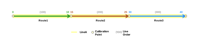
The following table details attributes for the routes (Route 1, Route 2, and Route 3):
| Route ID | From Date | To Date |
|---|---|---|
| Route1 | 1/1/2000 | <Null> |
| Route2 | 1/1/2000 | <Null> |
| Route3 | 1/1/2000 | <Null> |
The following diagram shows the creation of a spanning event feature. The first vertex intersects Route 1 at 5, which is resolved to the starting measure From Measure on Route 1, and the third vertex intersects Route 3 at 35, which is resolved to the ending measure To Measure on Route 3.
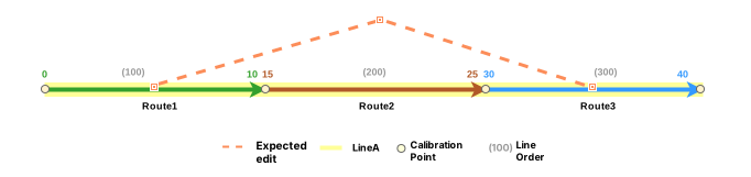
The following table details the spanning event after the edit:
| Event | From Route ID | To Route ID | From Date | To Date | From Measure | To Measure | Location Error | MAOP Design |
|---|---|---|---|---|---|---|---|---|
| Event1 | Route1 | Route3 | 1/1/2000 | <Null> | 5 | 35 | No Error | 800 |
| Event | From Route ID | To Route ID | From Date | To Date | From Measure | To Measure | Location Error | Speed Limit |
|---|---|---|---|---|---|---|---|---|
| Event1 | Route1 | Route3 | 1/1/2000 | <Null> | 5 | 35 | No Error | 55 |
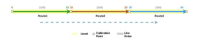
The following diagram shows the routes and the spanning event after the edit:
Spanning event creation resulting in a location error
The following diagram shows the routes before a line event is associated with it. In this case, Route 1 and Route 2 are on Line A, and Route A is on Line B. Spanning events must be on the same line in a line network.
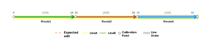
The following table details the route attributes. Route 1 and Route 2 are on Line A, and Route A is on Line B:
| Route ID | From Date | To Date |
|---|---|---|
| Route1 | 1/1/2000 | <Null> |
| Route2 | 1/1/2000 | <Null> |
| RouteA | 1/1/2000 | <Null> |
The following diagram shows the creation of a spanning event feature. The first vertex intersects Route 1 at 5, which is resolved to the starting measure on Route 1, and the third vertex intersects Route A at 35, which is not resolved to the ending measure on Route A because Route A is on Line B.

The following table provides an example of the Different From Route And To Route Line IDs value for the Location Error field. Events spanning routes must share the same line ID:
| Event | From Route ID | To Route ID | From Date | To Date | From Measure | To Measure | Location Error | MAOP Design |
|---|---|---|---|---|---|---|---|---|
| Event1 | Route1 | RouteA | 1/1/2000 | <Null> | 5 | 35 | Different From Route And To Route Line IDs | 800 |
| Event | From Route ID | To Route ID | From Date | To Date | From Measure | To Measure | Location Error | Speed Limit |
|---|---|---|---|---|---|---|---|---|
| Event1 | Route1 | RouteA | 1/1/2000 | <Null> | 5 | 35 | Different From Route And To Route Line IDs | 55 |
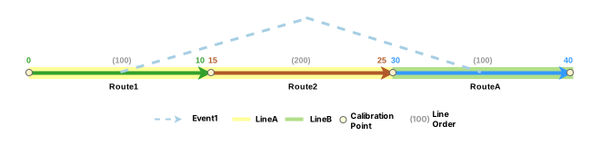
The following diagram shows Event 1 after the error:
Referent offset when using feature creation
The LRS events data model supports the configuration of event referent fields and their enablement using the Enable Referent Fields tool. Once referent fields are configured and enabled in a layer, referent locations are populated and persisted in that layer when events are added or edited.
When a line event is created using feature creation, the parent LRS Network is used as the FromRefMethod and ToRefMethod values, and the associated route is used as the FromRefLocation and ToRefLocation values. The start and end measures of the line event are used as the FromRefOffset and ToRefOffset values.
If either measure of a line event is updated, the corresponding offset value updates to reflect the new measure.
The examples below demonstrate the impact of adding a line event that has referent values enabled.
Before adding a line event with referents
The following diagram shows Route 1 before event creation:
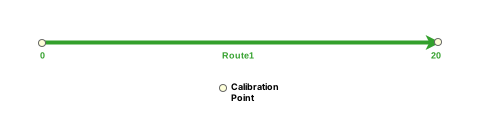
The following table provides details about the route:
| Route ID | From Date | To Date |
|---|---|---|
| Route1 | 1/1/2000 | <Null> |
After adding a line event with referents
The following diagram shows a line event that has been added to an event layer that has referents enabled:
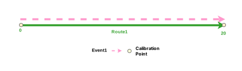
The following table provides details about the event referent fields after event creation:
| FromRefMethod | FromRefLocation | FromRefOffset | ToRefMethod | ToRefLocation | ToRefOffset |
|---|---|---|---|---|---|
| PipeSeriesNetwork | Route1 | 0 | PipeSeriesNetwork | Route1 | 20 |
| FromRefMethod | FromRefLocation | FromRefOffset | ToRefMethod | ToRefLocation | ToRefOffset |
|---|---|---|---|---|---|
| AllRoutes | Route1 | 0 | AllRoutes | Route1 | 20 |
The following table provides details about the other event fields after event creation:
| Event ID | From Date | To Date | From Measure | To Measure |
|---|---|---|---|---|
| Event1 | 1/1/2000 | <Null> | 0 | 20 |
You can edit the event using the attribute table so that it uses referents other than the default values. If subsequent route edits are made, the RefMethod and RefLocation values revert to the parent LRS Network and the route, respectively.