Use attribute propagation
Utility networks provide an advanced functionality known as attribute propagation that is used to represent and maintain variables such pipe pressure, line voltage, or phase when a subnetwork is updated, exported, or traced. Attribute propagation takes advantage of the network topology to calculate values from a source through connected elements of a subnetwork in the direction of flow.
Note:
Wavelength propagation is supported with the telecom domain network using the Propagated_BITWISE_AND function. To learn more, see Wavelength propagation.
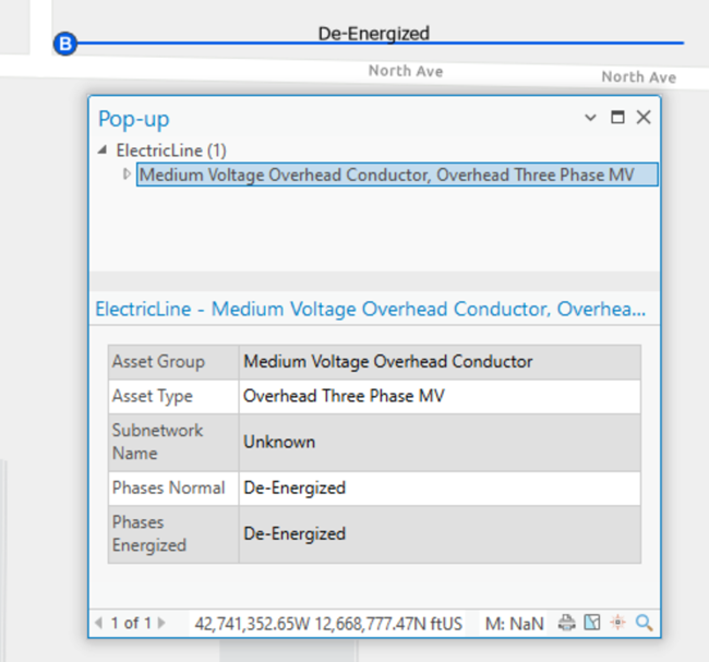
For example, consider an electric subnetwork consisting of a circuit breaker with a Normal Phases attribute value of ABC, a transformer, and a medium voltage overhead conductor. Before the subnetwork is updated, the Phases Energized field on the conductor is set as De-Energized.
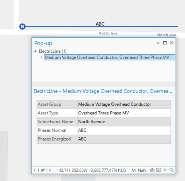
After the circuit breaker is set as the subnetwork controller and the update subnetwork operation is run, the Normal Phases value of ABC from the circuit breaker is propagated through the network, and the Phases Energized field value on the conductor is updated with the value of ABC.
Unlike traditional field calculations, propagation traverses the network topology to write values based on traversability from the controller.
Propagators are defined at the tier level as part of the subnetwork trace configuration using the Set Subnetwork Definition tool with network attributes. A network attribute for the propagated value is persisted inside the network topology when the topology is enabled or validated, and is associated with a value stored in an attribute on a network feature. Propagators derive values from the network attributes for features downstream of subnetwork controllers as the features are traversed during the update subnetwork, export subnetwork, or trace operation.
Note:
If a network attribute supports null values, null values encountered during propagation are ignored and have no impact on the value being propagated.
Propagated values are written to the features downstream of subnetwork controllers during the update subnetwork operation and are honored as condition barriers when performing subnetwork-based traces.
Note:
Attribute propagation is ignored when performing an upstream or downstream trace using digitized direction to model the flow of resources in the network.
The propagated values for features can also be returned to an output .json file when performing a trace or export subnetwork operation using the Features result types option and Include propagated values parameter. To learn more, see Configure a trace and Export subnetworks.
Note:
When working with enterprise geodatabases, the Include propagated values parameter requires ArcGIS Enterprise 12.1 or later.
When performing a trace, the propagators parameter is only available when using Python or creating a variable from a parameter in ModelBuilder. Propagator configurations are displayed as part of the trace configuration for tiers on the Network Properties tab. When a subnetwork is updated or traced, an operator is used to filter which features are considered. Several parameters are associated with a propagation configuration.
There are three Functions available for propagating a network attribute value:
Propagated_BITWISE_ANDPropagated_MINPropagated_MAX
Propagated_MIN and Propagated_MAX are typically used for analysis in traces using numeric values, whereas Propagated_BITWISE_AND is used primarily with subnetwork and circuit definitions in electric and telecom networks with numeric values that represent a bitset. To learn more, see Set Subnetwork Definition and Set Circuit Definition.
Note:
Propagation always starts from the subnetwork controller. When a propagator is evaluated and returns as false, the feature is considered a barrier and is not included in the result.
The following examples demonstrate scenarios in a source-based domain network; however, upstream and downstream could be reversed to apply to sink-based networks.
Propagated_BITWISE_AND
The Propagated_BITWISE_AND function takes the difference between two numeric values that represent a bitset. For example, in the electric domain, phase can be modeled using three bits: one for phase A, one for phase B, and one for phase C. These three bits together form a binary number 111, which when converted into decimal, yields the number 7. If one of the bits is de-energized (for example, bit B), leaving the other two bits energized (for example, bits A and C), the binary number becomes 101 (the 0 in the middle indicates B is de-energized), which when converted into decimal yields the number 5.
Consider a downstream trace on an electrical network where propagation is configured to update phase, where the network attribute Phases Current is assigned to the field phasescurrent.
The source circuit breaker is ABC. When the B phase is de-energized upstream, the propagator calculates the phase value of the downstream features to de-energize phase B as well, even though the network attribute of the feature may indicate phase B. This operation continues downstream with the trace as long as the operator is true.
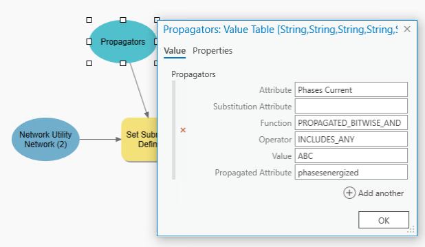
The example function illustrated below is as follows: "Phases Current" PROPAGATED_BITWISE_AND INCLUDES_ANY ABC "Phases Energized"
In this example, Phases Energized is the attribute updated following running Update Subnetwork. A line carrying phase B would be de-energized by the propagator and act as a barrier for a trace. Once the propagation method and operator returns false, the propagated value becomes 0 and the features are de-energized.
Propagated_MIN
The Propagated_MIN function takes the minimum value from the two numeric values being compared. This function should be used when a numeric value on the current feature needs to remain equal to or less than the value on the previous feature.
As an example, consider a downstream trace in an electric network where the network attribute MOV is assigned to the field maxoperatingvoltage. The trace begins with a MOV of 35 kV, which becomes the first propagated value. When the value of 25 kV is encountered, this minimum value is then propagated until it encounters another minimum value. This operation continues downstream, propagating the minimum value until the entire subnetwork is traced or the condition set by the operator is met.
The example function illustrated below is as follows: "MOV" PROPAGATED_MIN IS_GREATER_THAN 15 "MAXVOLTAGE".
This configuration tells the system to continue propagating while MOV remains greater than 15 kV. In this example, MAXVOLTAGE is the attribute updated when the Update Subnetwork tool runs, and a value of 15 kV or less would act as a barrier, terminating the trace.
Propagated_MAX
The Propagated_MAX function takes the maximum value from the two numeric values being compared. This function should be used when a numerical value on the current feature needs to remain equal to or greater than the value on the previous feature.
Consider the same electric network where MOV is a network attribute assigned to the maxoperatingvoltage field. An engineer considering upgrading the voltage on a circuit may want to run a trace to help them understand how much equipment might need to be changed as part of the project. This could be done using a propagator to update MAXVOLTAGE along the line with a trace, as long as it did not exceed 30 kV using the PROPAGATED_MAX function with the network attribute MOV as follows: "MOV" PROPAGATED_MAX IS_LESS_THAN_OR_EQUAL_TO 30 "MAXVOLTAGE".
This configuration tells the system to continue propagating while MOV remains less than 30 kV. In this example, MAXVOLTAGE is the attribute updated while the Update Subnetwork tools runs, and a value greater than 30 kV would act as a barrier, terminating the trace.
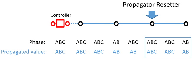
Propagator resetters
The Propagator Resetter network category can be used to designate features in the network which reset the propagated attribute value when discovered as part of a trace. During propagation, if features with the propagator resetter category are discovered, the values from the resetter features become the propagated attribute values.
Note:
The Propagator Resetter network category is supported with Utility Network Version 8 and later.
Set up phase propagation
Attribute propagation is configured by the administrator of a utility network. To configure attribute propagation, the following steps must be completed:
For each class in your network that will use propagation, create a field to store measurable or changing asset information—for example,
Phases Currentin an electrical network.Configure a coded value domain and assign this to the fields you create in step 1.
This will serve as the initial values, for example A = 4, B = 2 and C = 1, including values for the various combinations. The following shows an example configuration of the coded value domain for a 3-bit system:
Code
Description
0
De-energized
1
C
2
B
3
BC
4
A
5
AC
6
AB
7
ABC
Create an inline network attribute and specify the domain from step 2 using the Add Network Attribute tool.
Assign the network attribute to the fields created in step 1 using the Set Network Attribute tool.
Optionally, create another field on each of the classes from step 1 to capture and store the propagated phase value, commonly called
Phases Energizedin an electrical network.Assign the domain created in step 2 to the fields created in step 5.
Use the Set Subnetwork Definition tool to define how propagation will operate during analytic events.
This can be done by adding the Set Subnetwork Definition tool to a model in ModelBuilder.
Right-click the Set Subnetwork Definition tool in the model and choose Create Variable > From Parameter > Propagators.
Double-click the Propagators parameter added to the model and populate the attributes appropriately.