Use wavelength propagation
Propagation supports wavelength modeling in the telecom domain network with path and circuit traces. Wavelengths are conceptually similar to phases in an electric network in that they provide a logical subdivision of an asset that can control flow. As with phases in electric, wavelengths are modeled as a network attribute on features in the network.
Propagators can be configured to calculate wavelength values on network features and define high level traversability constraints in the network. Condition barriers can then be configured as part of the trace operation to use the propagated values and provide more granular control over what is returned by the trace.
Each wavelength is represented as a bit in a network attribute. For example, with coarse wavelength division multiplexing (CWDM), there are 18 standard wavelengths, represented by 18 bits. Dense wavelength division multiplexing (DWDM) can be similarly represented using additional bits to represent the wavelengths.
In traditional domain networks, attribute propagation begins at the subnetwork controller. In contrast, wavelength propagation works with a path or circuit trace to spans outward from the starting point and locate ports assigned the Circuit Location network category. Wavelength values are then propagated outward from the circuit locations up to max hops to traverse the network using wavelength values in a circuit or path.
Note:
The Propagated_BITWISE_AND function is used to propagate the wavelength network attribute values using a numeric values that represent a bitset. Propagated_MIN and Propagated_MAX functions are not supported for use with the telecom domain network.
Set up wavelength propagation
Propagation is configured by the administrator of a utility network. To configure wavelength propagation, the following steps must be completed:
Configure a wavelength scheme for use in your network.
Edit network features to update the
Wavelengthsnetwork attribute value to reflect the supported wavelengths for the feature.Define propagators using the Set Circuit Properties or Trace tool:
The Set Circuit Properties tool is best used to define propagators which will apply to all circuit traces performed in the telecom domain network.
The Trace tool is best used to define propagators which apply to a specific path or circuit trace.
Configure a path or circuit trace to use the configured propagator.
Condition Barriers can be configured as part of the trace to provide more granular control over what is traced within the propagated result. This provides the flexibility to control trace behavior without having to modify the underlying propagators.
Note:
When performing a circuit trace, if the start and stop locations correspond to junctions or junction objects assigned the Circuit Location network category with wavelength values, the trace compares the wavelength values at both locations. If the values do not match, the trace fails.
Propagated_BITWISE_AND
The Propagated_BITWISE_AND function performs a bitwise AND binary operation between two numeric values that represent a bitset. In the telecom domain, if the input wavelength string contains a wavelength name, the bit position corresponding to the wavelength ID is set to true.
For example, consider the following wavelength scheme to model CWDM:
| ID | Name | Wavelength (nm) |
|---|---|---|
| 1 | C27 | 1270.00 |
| 2 | C29 | 1290.00 |
| 3 | C31 | 1310.00 |
| 4 | C33 | 1330.00 |
| 5 | C35 | 1350.00 |
| 6 | C37 | 1370.00 |
| 7 | C39 | 1390.00 |
| 8 | C41 | 1410.00 |
| 9 | C43 | 1430.00 |
| 10 | C45 | 1450.00 |
| 11 | C47 | 1470.00 |
| 12 | C49 | 1490.00 |
| 13 | C51 | 1510.00 |
| 14 | C53 | 1530.00 |
| 15 | C55 | 1550.00 |
| 16 | C57 | 1570.00 |
| 17 | C59 | 1590.00 |
| 18 | C61 | 1610.00 |
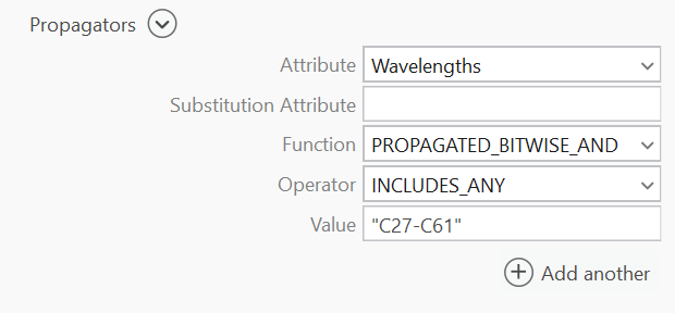
You can configure the following propagator for the circuits in your telecom domain network to propagate all wavelengths within the CWDM scheme using the Set Circuit Properties or Trace tool as: Wavelengths PROPAGATED_BITWISE_AND INCLUDES_ANY "C27-C61".
Note:
When performing a trace, the Propagators parameter is only available when using Python or creating a variable from a parameter in ModelBuilder. Any propagators configured in a telecom domain network's circuit properties are loaded to the tool when configuring a circuit trace and can be modified as needed. Propagator configurations are displayed as part of the circuit properties for a telecom domain network on the Network Properties tab in the Utility Network properties.
Bitwise operators for wavelengths
There are two bitwise operators available for use with wavelength propagation:
Includes any—Specifies that one (or more) of the input wavelength value bits is true on one (or more) units of the grouped object.
Does not include any—Specifies that all input wavelength value bits are false for all units of the grouped object.
Since individual units in a grouped object can represent different wavelength assignments, the logical representation of the bitset for grouped objects takes into account each unit and the assigned Wavelengths attribute value. An example is displayed below with the bitset values for the grouped junction object which has been configured with a wavelength attribute value of [1,4, "C27"]:
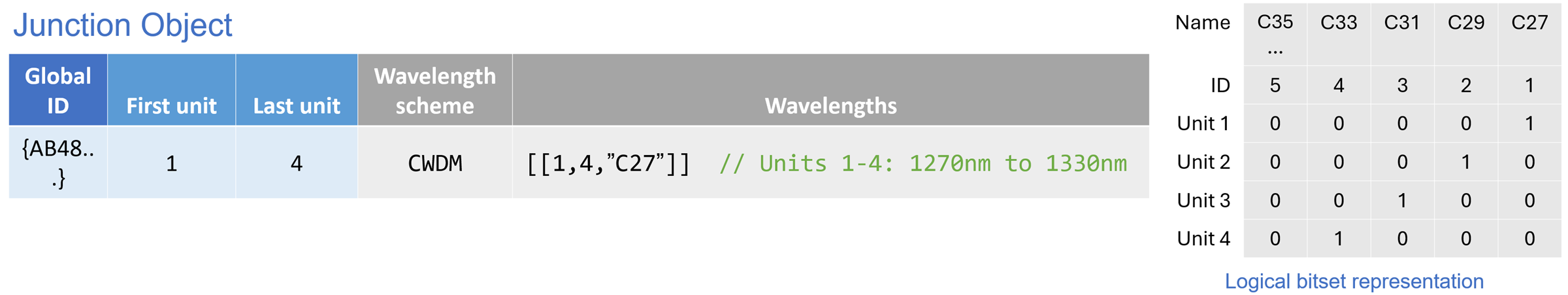
Consider a scenario where you have configured a propagator to support all wavelengths in the CWDM scheme above. You then configure a trace using a condition barrier on the Wavelengths attribute as "Wavelengths INCLUDES_ANY SPECIFIC_VALUE "C35" #". This condition would evaluate to False for the junction object because all units in the propagated value are False. If you were to configure the condition barrier as "Wavelengths DOES_NOT_INCLUDE_ANY SPECIFIC_VALUE "C35" #", the propagator would evaluate to True and the junction object would not act as a barrier because the bits for C35 on all units are False.
Example
Consider the following example demonstrating how wavelength propagation calculates wavelength values from a circuit location during a path trace.
A wavelength scheme for CWDM as outlined in the section above is configured.
A propagator is configured in the circuit properties as
PROPAGATED_BITWISE_AND INCLUDES_ANY "C27-C61".A circuit location port (JO1) with four units is assigned wavelengths as [[1, 4, "C27"]] — meaning Unit 1 is assigned C27, Unit 2 is assigned C29, Unit 3 is assigned C31, and Unit 4 is assigned C33.
When a path trace is run from the starting point on EO1, the trace spans outward to identify ports assigned the Circuit Location network category. The circuit location at JO1 is identified, and its wavelength values are used to calculate the wavelength values for the features in the network (up to max hops) to calculate the path.
As the trace continues through EO1, the propagated wavelength values from JO1 are carried to JO2. At JO2, the units and their wavelengths are split across two paths: units 1 and 2 continue along EO2 toward JO3 and the stopping point, while units 3 and 4 follow EO3 toward JO4.
At JO4, which also has wavelength values assigned, the propagated values from JO1 are compared against the local values using the PROPAGATED_BITWISE_AND function. This returns the intersection — only the wavelength bits that are true in both the propagated and local values are retained. The resulting values are then carried through EO4 until the trace stops at JO5.