Work with utility network properties
You can access properties of the utility network from both the Contents and Catalog panes in ArcGIS Pro. When opened from the Contents pane, the Layer Properties dialog box displays information about layer-specific properties as well as dataset properties. Opening the Utility Network Properties dialog box from the Catalog pane displays only the dataset properties for the utility network.
Access utility network properties
The Layer Properties and Utility Network Properties dialog boxes provide the same dataset properties for the utility network. However, when you access Layer Properties from the Contents pane, additional tabs such as General, Metadata, and Source allow you to set layer properties common to all map layers.
Access properties from the Contents pane
To open the Layer Properties dialog box using the utility network layer's context menu in the Contents pane, complete the following steps
Ensure that the utility network is added to an active map. If the utility network layer is not present in a map, from the Catalog pane, right-click the utility network dataset
 and select Add to new map or Add to current map.
The utility network and related network classes are added to a new or existing map view.
In the Contents pane, right-click the utility network layer and select Properties.
The Layer Properties dialog box appears.
The following tabs are available on the Layer Properties dialog box:
General
Metadata
Source
Network Properties
Network Diagrams
Time
To expand the dialog box, double-click the top menu bar.
Access properties from the Catalog pane
To access the Utility Network Properties dialog box from the utility network dataset's contextual menu under Databases ![]() in the Catalog pane, complete the following steps:
in the Catalog pane, complete the following steps:
With ArcGIS Pro open, browse to the Catalog pane and open the geodatabase and feature dataset containing the utility network.
In the Catalog pane, right-click the utility network dataset and select Properties.
The Utility Network Properties dialog box appears.
The following tabs are available on the Utility Network Properties dialog box:
Network Properties
Network Diagrams
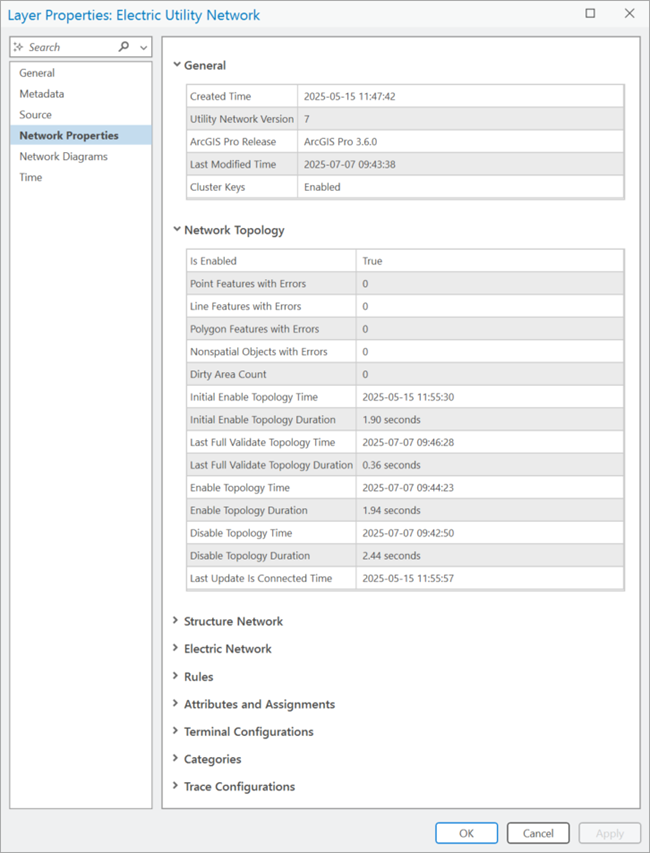
Network Properties tab
The Network Properties tab provides information about the creation date, network topology, domain networks, rules, diagram templates, and other important metadata regarding the current configuration of the utility network.
The following sections are included on the Network Properties tab for the utility network:
General
The General section includes information about the creation and last modified times and version information for the utility network in the following sections:
Created Time
Utility Network Version
ArcGIS Pro Release
Last Modified Time
Portal Utility Network Owner (see note below)
Upgraded (see note below)
Partition ID Size - Utility Network Version 8 only.
Max Wavelengths - Utility Network Version 8 only.
Note:
When working with an enterprise geodatabase, the Portal Utility Network Owner and Upgraded properties are only available on the Network Properties tab when accessed from a database connection as the database utility network owner. The portal utility network owner is helpful when performing configuration and publishing tasks.
Network Topology
The Network Topology section includes information about whether the network topology is enabled, the dirty area count, and error counts. In addition, the following specific operations are recorded as they are completed using the utility network:
Is Enabled
Point Features with Errors
Line Features with Errors
Polygon Features with Errors
Nonspatial Objects with Errors
Dirty Area Count
Initial Enable Topology Time and Duration
Enable Topology Time and Duration
Last Full Validate Topology Time and Duration
Last Partial Validate Topology Time and Duration
Disable Topology Time and Duration
Last Update Is Connected Time
Structure Network
The Structure Network section includes the following subsections:
General—Information about the structure network
Created Time
Name
Alias Name
Structure network datasets
Structure network dataset name
Structure Junction
Structure Line
Structure Boundary
Structure Junction Object
Structure Edge Object
The following properties for each dataset are displayed:
Asset Group Name
Asset Type Name
Category (all except boundary)
Network Edge Connectivity Policy (line and edge object only)
Container Split Policy (line and edge object only)
Domain Network
For each domain network that is part of the utility network, there is a <Domain network name> Network section.
This section includes the following subsections:
General—Information about the domain network
Created Time
Name
Alias Name
Tiers —Tiers that have been created with their associated subnetwork definition.
Tier Name
Tier Rank
Tier Topology Type
-
Manage IsDirty: True | False
Update Structure Network Containers: True | False
Update Domain Network Containers: True | False
Edit Mode in Default: Without Eventing | With Eventing (enterprise, file, and mobile geodatabases)
Edit Mode in Version: Without Eventing | With Eventing (enterprise geodatabase only)
Valid Subnetwork Controllers
Device
Junction Object
Subnetwork Field Name—Domain networks with hierarchical tier definitions only
Valid Devices
Valid Lines
Aggregated Lines for SubnetLine Feature Class
Valid Junctions
Valid Junction Objects
Valid Edge Objects
Diagram Templates
Trace Configuration
Created Time
Domain network datasets
Domain network class name
<Domain network name> Device
<Domain network name> Junction
<Domain network name> Line
<Domain network name> Assembly
<Domain network name> Junction Object
<Domain network name> Edge Object
Note:
The domain network classes are prefixed with the name provided for the domain network, for example, ElectricDistributionDevice.
The following properties are displayed for each class:
Asset Group Name
Asset Type Name
Network Edge Connectivity Policy (line and edge object only)
Terminal Configuration Name (device and junction object only)
Container Split Policy (line and edge object only)
When working with a telecom domain network, this section includes the following subsections:
General—Information about the domain network
Created Time
Name
Alias Name
Color Sets—Information about the color sets that have been added to a telecom domain network for use by color schemes:
Color Set Name
Color Code Name
Color Code Label
Hex Code
Color schemes—Information about the color schemes that have been added to a telecom domain network:
Color Scheme Name
ID
Group Delimiter
Levels
Group Level
Group Name
Labels
Capacity
Delimiter
Circuit Properties—Information about the circuit properties configured for the telecom domain network. These are honored when creating or modifying circuits, and when running a verify, export, or circuit trace operation.
Share circuit locations
Import circuits as clean
Trace Configuration
User Attributes Marking Circuits Dirty
Telecom Object Divide Policy—Information about the divide policies applied to fields for grouped objects:
Class Name
Field Name
Policy
Telecom Object Combine Policy—Information about the combine policies applied to fields for grouped objects:
Class Name
Field Name
Policy
Wavelength Schemes —Information about the wavelength schemes created to model and trace network features:
Wavelength Scheme Name
Wavelengths
Domain network datasets
Domain network class name
<Domain network name> Device
<Domain network name> Junction
<Domain network name> Line
<Domain network name> Assembly
<Domain network name> Junction Object
<Domain network name> Edge Object
Note:
The domain network classes are prefixed with the name provided for the domain network, for example, TelcoDevice.
Rules
The Rules section lists the existing network rule base for the utility network. This section is divided by network rule type, as shown below. Within each rule type is a Sort By filter for easier viewing.
Junction-Junction Connectivity
Junction-Edge Connectivity
Edge-Junction-Edge Connectivity
Containment
Structural Attachment
Within each rule type, the table contains all the properties for that rule. See View network rules for more details.
Attributes and Assignments
The Attributes and Assignments section includes the network attributes and assignments for the utility network. As network attributes are created in the utility network, they are listed in the Attributes table.
Name
Field Type
Nullable
Inline (Bit Size)
Domain Name
Created Time
When network attributes are assigned to a particular feature class and field, they populate the Assignments table as follows:
Attribute Name
Class Name
Field Name
Terminal Configurations
The Terminal Configurations section includes a table that displays the existing terminal configurations for use with traditional domain networks in the utility network and includes information about the following properties of each terminal configuration as follows:
Name
Directionality Model
Terminals (ID/Name/Upstream Terminal)
Valid Paths
Created Time
For information about which asset types are assigned a specific terminal configuration, review the device feature class or junction object table properties for the specific traditional domain network (Terminal Configuration Name).
Categories
The Categories section includes the names of existing network categories in the utility network. For information about which asset types are assigned a specific network category, review the Category column for the specific feature class or table in the Structure Network and <Domain name> Network sections. The information provided for the categories is as follows:
Name
Created Time
Trace Configurations
The Trace Configurations section includes information about the named trace configurations in the utility network as follows:
Name
Description
Creator
Created Time
Tags
Network Diagrams tab
The Network Diagrams tab includes the Diagram Templates table. This table includes the names of existing diagram templates in the utility network, and various information and properties for each diagram template.