Add a line event by route and measure
 Available with the Linear Referencing license.
Characteristics of a route can be represented as a line event with start and end measure information along the route.
Use the Add Line Event tool to add line events to a line event layer. You can also add events that span multiple routes on a line.
Characteristics of a route, such as speed limit and functional class, can be represented as a line event with start and end measure information along the route.
Use the Add Line Event tool to add line events to a line event layer.
Before using this tool to edit a feature service, you must share branch versioned linear referencing system (LRS) data as a web layer. If the feature service is not yet published, see Share as web layers.
Add a line event using route and measure
The example in the following workflow demonstrates adding a line event that spans routes using the Route and Measure method.
The following diagram shows the routes that belong to a line before event creation:
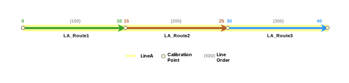
The following table provides details about attributes for the routes (LA_Route 1, LA_Route 2, and LA_Route 3) that belong to Line A:
| Route Name | From Date | To Date |
|---|---|---|
| LA_Route1 | 1/1/2000 | <Null> |
| LA_Route2 | 1/1/2000 | <Null> |
| LA_Route3 | 1/1/2000 | <Null> |
The following workflow details line event creation from 12 to 18 on Route 1 using the Route and Measure method.
The following diagram shows the route before event creation:
The following table provides details about the route before event creation:
| Route ID | From Date | To Date |
|---|---|---|
| 10100000123000001 | 1/1/2000 | <Null> |
To add a line event using route and measure, complete the following steps:
Start ArcGIS Pro and open a project with LRS data in the map.
Zoom to the location where you want to add a line event.
On the Linear Referencing tab, in the Event Editing group, click Add Line
 .
The Add Line Event pane appears with Route and Measure as the default method for the From Method and To Method parameters.
When using the Route and Measure method, the measure location is based on the measure values from the selected route.
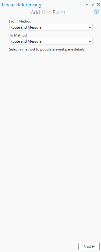
Click Next.
The tool parameters appear in the pane.
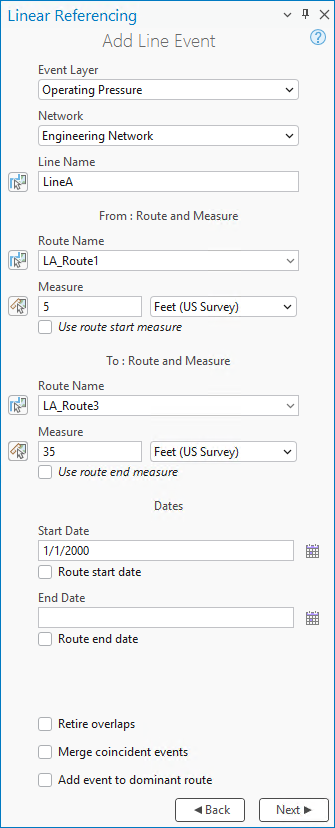
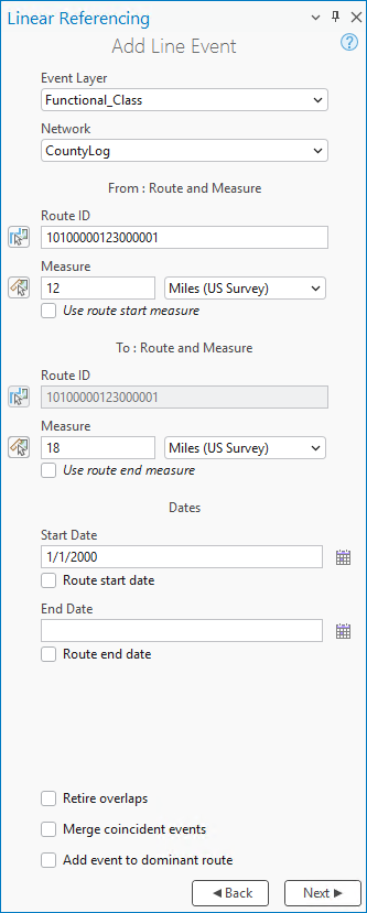
Click the Event Layer drop-down arrow and choose a line event layer.
The Network parameter is automatically populated based on the specified event layer. The LRS Network serves as the source linear referencing method (LRM) to define the input measures for the event.
If you are using a line network, click Choose line from map
 and click a route on the map.
You can also provide a line name in the Line Name text box.
The Line Name text box is populated.
In the From: Route and Measure section, specify a starting route by doing one of the following:
Click Choose route from map
and click the starting route on the map.Provide a route name in the Route Name text box.
Click the Route Name drop-down arrow and choose a route.
If you are using a line network, the starting route must belong to the same line.
If multiple routes exist at the edit location, select one of the routes in the Select a Route dialog box.
Tip:
After clicking Choose route from map
or Choose measure from map  , you can hover over the routes to see the route and measure at the location of the pointer. You can set map scale options for display of route and measure information in the Linear Referencing options.
When hovering near a feature, you can turn snapping on to improve the accuracy of the pointer.
Note:
If a message regarding acquiring locks or reconciling appears, it means that conflict prevention is enabled. After you select a route, the tool attempts to release the route lock if the active user acquires the route lock in a different named version and the releasable status value is Yes.
In the From: Route and Measure section, specify a route by doing one of the following:
Click Choose route from map
and click the route on the map.Provide a route ID in the Route ID text box.
If multiple routes exist at the edit location, select one of the routes in the Select a Route dialog box.
Tip:
After clicking Choose route from map
or Choose measure from map , you can hover over the routes to see the route and measure at the location of the pointer. You can set map scale options for display of route and measure information in the Linear Referencing options.When hovering near a feature, you can turn snapping on to improve the accuracy of the pointer.
Note:
If a message regarding acquiring locks or reconciling appears, it means that conflict prevention is enabled. After you select a route, the tool attempts to release the route lock if the active user acquires the route lock in a different named version and the releasable status value is Yes.
Specify the start measure for the new line event by doing one of the following:
Enter a value in the Measure text box.
Click Choose measure from map
and click a location along the route on the map.Check the Use route start measure check box.
A green point appears on the map at that measure location.
In the To: Route and Measure section, specify an ending route by doing one of the following:
Click Choose route from map
and click the ending route on the map.Provide a route name in the Route Name text box.
Click the Route Name drop-down arrow and choose a route.
If you are using a line network, the ending route must belong to the same line.
If multiple routes exist at the edit location, select one of the routes in the Select a Route dialog box.
In the To: Route and Measure section, specify the end measure for the new line event by doing one of the following:
Enter a value in the Measure text box.
Click Choose measure from map
and click a location along the route on the map.Check the Use route end measure check box.
A red point appears at the end measure location on the map. The event is created between the green and the red points.
Optionally, change the start date by doing one of the following:
Provide the start date in the Start Date text box.
Click Calendar
 and choose the start date.
Check the Route start date check box.
The default start date is the current date.
Optionally, specify the end date of the line event by doing one of the following:
Provide the end date in the End Date text box.
Click Calendar
and choose the end date.Check the Route end date check box.
Double-click in the End Date text box to use the current date.
If you do not provide an end date, the event remains valid from the start date into the future.
Optionally, choose any applicable data validation option to prevent erroneous input while characterizing a route with line events:
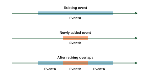
- Retire overlaps—The measure, start date, and end date of existing events are adjusted to prevent overlaps with respect to time and measure values once the new line event or events are created. For more information, refer to the Retire overlaps scenario section below.
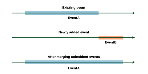
- Merge coincident events—When all attribute values for a new event are exactly the same as an existing event, and if the new event is adjacent to or overlapping an existing event in terms of its measure values, and its time slices are coincident or overlapping, the new event is merged with the existing event and the measure range is expanded accordingly. For more information, refer to the Merge coincident events scenario section below.
Click Next.
The attributes for the line event layer appear under the Manage Attributes section.
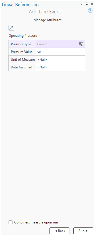
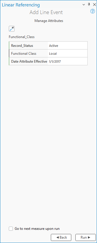
Optionally, provide attribute values for the event.
Tip:
Click Copy attribute values by selecting event on the map
 , and click an existing line event belonging to the same event layer on the map to copy event attributes from that event.
Coded value domains, range domains, subtypes, contingent values, and attribute rules are supported when configured for a field.
Optionally, check the Go to next measure upon run check box to start your next edit at the end measure location of the previous edit. The To Method value and its populated information from the previous edit carry over to the next edit as the From Method value and its populated information.
For example, if you use a From Method value of Location Offset and a To Method value of Coordinates to add a line event, enabling this option starts your next edit with From Method and To Method values of Coordinates with the coordinates information from the previous edit in the From: Coordinates section.
Click Run.
A confirmation message appears, and the new line event appears on the map.
The following table provides details after adding the line event that spans routes:
| Event | From Route Name | To Route Name | From Date | To Date | From Measure | To Measure | Location Error | Pressure Type | Pressure Value |
|---|---|---|---|---|---|---|---|---|---|
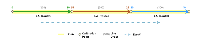
| Event1 | LA_Route1 | LA_Route3 | 1/1/2000 | <Null> | 5 | 35 | No Error | Design | 500 |
The following diagram shows the routes and the line event that spans routes after the tool is run:
The following table provides details about the new line event:
| Event | Route ID | From Date | To Date | From Measure | To Measure |
|---|---|---|---|---|---|
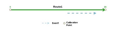
| Event1 | 10100000123000001 | 1/1/2017 | <Null> | 12 | 18 |
The following diagram shows the route and its associated event after the line event is added:
Referent offset when using the Route and Measure method
The LRS events data model supports the configuration of event referent fields and their enablement using the Enable Referent Fields tool. Once referent fields are configured and enabled in a layer, referent locations are populated and persisted in that layer when events are added or edited.
When a line event is created using the Route and Measure method in a referent-enabled layer, the parent LRS Network is used by default as the FromRefMethod and ToRefMethod values, and the route is used as the FromRefLocation and ToRefLocation values. The start and end measures of the line event are used as the FromRefOffset and ToRefOffset values.
If either measure of a line event is updated, the corresponding offset value updates to reflect the new measure.
The examples below demonstrate the impact of adding a line event that has referent values enabled.
Before adding a line event with referents
The following diagram shows the routes before event creation:

The following table provides details about the routes:
| Route ID | From Date | To Date | From Measure | To Measure |
|---|---|---|---|---|
| R1 | 1/1/2000 | <Null> | 0 | 5 |
| R2 | 1/1/2000 | <Null> | 7 | 12 |
| R3 | 1/1/2000 | <Null> | 13 | 18 |
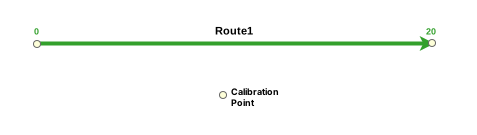
The following diagram shows the routes before event creation:
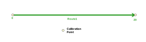
The following table provides details about the route:
| Route ID | From Date | To Date | From Measure | To Measure |
|---|---|---|---|---|
| Route1 | 1/1/2000 | <Null> | 0 | 20 |
After adding a line event with referents
The following diagram shows the route and an associated event:

The following table provides details about the event referent fields after event creation:
| FromRefMethod | FromRefLocation | FromRefOffset | ToRefMethod | ToRefLocation | ToRefOffset |
|---|---|---|---|---|---|
| Engineering Network | R1 | 0 | Engineering Network | R3 | 18 |
The following table shows the other event fields after event creation:
| From Route ID | To Route ID | From Date | To Date | From Measure | To Measure |
|---|---|---|---|---|---|
| R1 | R3 | 1/1/2000 | <Null> | 0 | 18 |
The following diagram shows the route and an associated event:
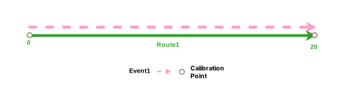
The following table shows the event fields after event creation:
| Event ID | From Date | To Date | From Measure | To Measure | FromRefMethod | ToRefMethod | FromRefLocation | ToRefLocation | FromRefOffset | ToRefOffset | Speed |
|---|---|---|---|---|---|---|---|---|---|---|---|
| Event1 | 1/1/2000 | <Null> | 0 | 20 | CountyLog | CountyLog | Route1 | Route1 | 0 | 20 | 45 |
You can edit the event using the attribute table so that it uses referents other than the default values. If subsequent route edits are made, the RefMethod and RefLocation values revert to the parent LRS Network and the route, respectively.
Retire overlaps scenario
The example below demonstrates adding line events that overlap when the Retire overlaps option is checked.
In this example, an existing DOT Class event, Event A, spans R2 and R3. Event A has a start date of 1/1/2000. This example demonstrates the impact of adding a second DOT Class event, Event B, which has overlapping measures.
The following diagram shows the routes and Event A:
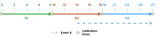
The following table provides details about the attributes of Event A:
| Event ID | From Route ID | From Measure | To Route ID | To Measure | From Date | To Date | Class Type |
|---|---|---|---|---|---|---|---|
| EventA | R2 | 14 | R3 | 27 | 1/1/2000 | <Null> | Class 1 |
The following diagram shows Event B that has a start date of 1/1/2005:
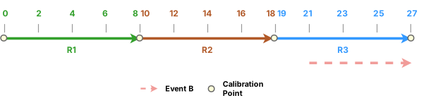
The following table provides details about the attributes of Event B:
| Event ID | From Route ID | From Measure | To Route ID | To Measure | From Date | To Date | Class Type |
|---|---|---|---|---|---|---|---|
| EventB | R3 | 21 | R3 | 27 | 1/1/2005 | <Null> | Class 2 |
The following diagram shows the impact of checking the Retire Overlaps option when adding Event B:
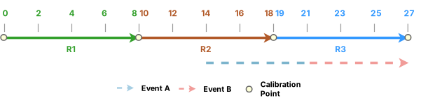
The following table provides details about event attributes after the Retire Overlaps option is checked, and Event B is added:
| Event ID | From Route ID | From Measure | To Route ID | To Measure | From Date | To Date | Class Type |
|---|---|---|---|---|---|---|---|
| EventA | R2 | 14 | R3 | 27 | 1/1/2000 | 1/1/2005 | Class 1 |
| EventA | R2 | 14 | R3 | 21 | 1/1/2005 | <Null> | Class 1 |
| EventB | R3 | 21 | R3 | 27 | 1/1/2005 | <Null> | Class 2 |
The example below demonstrates adding line events that overlap when the Retire overlaps option is checked.
In this example, Route 1 has an existing Speed Limit event that has dates from 1/1/2000 to <Null>. The impact of adding a second Speed Limit event with overlapping measures is demonstrated.
The following diagram shows the route and the existing event:
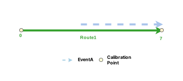
The following table provides details about Event A before the edit:
| Event ID | Route ID | From Measure | To Measure | From Date | To Date | Speed |
|---|---|---|---|---|---|---|
| EventA | Route1 | 3 | 7 | 1/1/2000 | <Null> | 65 |
The following diagram shows the route and a second event that is added with dates from 1/1/2005 to <Null>:
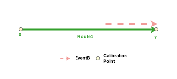
The following table provides details about EventB after the edit:
| Event ID | Route ID | From Measure | To Measure | From Date | To Date | Speed |
|---|---|---|---|---|---|---|
| EventB | Route1 | 5 | 7 | 1/1/2005 | <Null> | 45 |
The following diagram shows the impact of checking the Retire overlaps option:
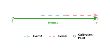
The following table provides details after the Retire overlaps option is checked:
| Event ID | Route ID | From Measure | To Measure | From Date | To Date | Speed |
|---|---|---|---|---|---|---|
| EventA | Route1 | 3 | 7 | 1/1/2000 | 1/1/2005 | 65 |
| EventA | Route1 | 3 | 5 | 1/1/2005 | <Null> | 65 |
| EventB | Route1 | 5 | 7 | 1/1/2005 | <Null> | 45 |
Merge coincident events scenario
The example below demonstrates adding line events that have coincident measures when the Merge coincident events option is checked.
In this example, an existing DOT Class event, Event A, spans R1 and R2. Event A has a start date of 1/1/2000. This example demonstrates the impact of adding a second DOT Class event that has coincident measures.
The following diagram shows the routes and Event A:
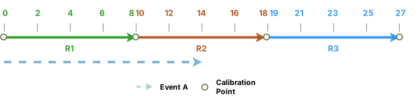
The following table provides details about the attributes of Event A:
| Event ID | From Route ID | From Measure | To Route ID | To Measure | From Date | To Date | Class Type |
|---|---|---|---|---|---|---|---|
| EventA | R1 | 0 | R2 | 14 | 1/1/2000 | <Null> | Class 1 |
The following diagram shows the routes and the new event to be added:
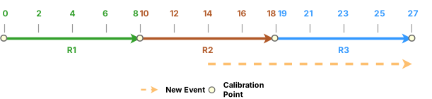
The following table provides details about the attributes of the new event:
| Event ID | From Route ID | From Measure | To Route ID | To Measure | From Date | To Date | Class Type |
|---|---|---|---|---|---|---|---|
| [NewEvent input] | R2 | 14 | R3 | 27 | 1/1/2000 | <Null> | Class 1 |
The following diagram shows the impact of checking the Merge coincident events option when adding the new event:
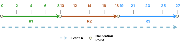
The following table provides details about the attributes of Event A after the new event is merged with it:
| Event ID | From Route ID | From Measure | To Route ID | To Measure | From Date | To Date | Class Type |
|---|---|---|---|---|---|---|---|
| EventA | R1 | 0 | R3 | 27 | 1/1/2000 | <Null> | Class 1 |
The example below demonstrates adding line events that have coincident measures when the Merge coincident events option is checked.
In this example, Route 1 has an existing Speed Limit event that has dates from 1/1/2000 to <Null>. The impact of adding a Speed Limit event with coincident measures when Merge coincident events is checked is demonstrated.
The following diagram shows the route and the existing event:
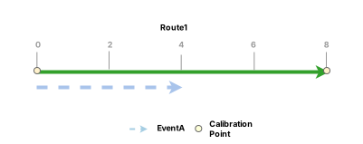
The following table provides details about Event A before the edit:
| Event ID | Route ID | From Measure | To Measure | From Date | To Date | Speed |
|---|---|---|---|---|---|---|
| EventA | Route1 | 0 | 4 | 1/1/2000 | <Null> | 65 |
The following diagram shows the route and a second event that is added with dates from 1/1/2000 to <Null>:
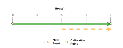
The following table provides details about the new input:
| Event ID | Route ID | From Measure | To Measure | From Date | To Date | Speed |
|---|---|---|---|---|---|---|
| [NewEvent input] | Route1 | 4 | 8 | 1/1/2000 | <Null> | 65 |
The following diagram shows the impact of checking the Merge coincident events option when adding the new event:
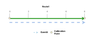
The following table provides details after the new event measures are merged with Event A:
| Event ID | Route ID | From Measure | To Measure | From Date | To Date | Speed |
|---|---|---|---|---|---|---|
| EventA | Route1 | 0 | 8 | 1/1/2000 | <Null> | 65 |