Set starting points, stopping points, and barriers
One or more starting points must be used in utility network trace operations to define the starting location of a trace. You can also use stopping points to specify the end of a path or create barriers to represent a location in the network beyond which the trace cannot travel. Starting points, stopping points, and barriers are also referred to collectively as trace locations. To learn more, see Trace utility networks, Starting points, Stopping points, Barriers, and Trace results.
In the Trace pane, three tabs are available for specifying starting points, stopping points, and barriers to serve as trace locations. You can use the Add features option ![]() to manually select network features on a map, or you can use the Add selected option
to manually select network features on a map, or you can use the Add selected option ![]() to set preselected network features on a map or attribute table as trace locations. Starting points, stopping points, and barriers use the UN_Temp_Starting_Points, UN_Temp_Stopping_Points, and UN_Temp_Barriers feature class, respectively, to store these features in the project's default geodatabase.
to set preselected network features on a map or attribute table as trace locations. Starting points, stopping points, and barriers use the UN_Temp_Starting_Points, UN_Temp_Stopping_Points, and UN_Temp_Barriers feature class, respectively, to store these features in the project's default geodatabase.
Requirements
The following requirements must be met to set starting points, stopping points, and barriers:
Trace locations must use utility network features.
The network topology must be enabled.
Set starting points, stopping points, and barriers using the Trace pane
Set starting points, stopping points, and barriers using the Trace pane in one of the following ways:
Add features by manually selecting them in the map view.
Add selected features or objects from the map view or attribute table.
The Add Trace Locations tool can also be used to define trace locations when working with network features. This tool allows you to select specific features or objects and export them to a feature class, as a consistent set of trace locations for repeated trace operations in a script or model. Alternatively, you can specify starting points, stopping points, and barriers using a user-defined feature class or table that meets certain requirements. To learn more, see Starting points, Stopping points, and Barriers.
Note:
Lines (edge elements) in the utility network support a single starting point, stopping point, and barrier. If more than one trace location of each type is specified for an edge element, only the last starting point, stopping point, and barrier added are honored; all others are ignored.
Add features by manually selecting them in the map view
You can manually select network features on a map to set them as starting points, stopping points, or barriers. Complete the steps below if the features you want to set as trace locations are not selected on the map. This workflow uses the default setting on the Start, Stop, and Barriers tabs in the Trace pane, with Auto Apply checked.
On the Utility Network tab, in the Tools group, click Trace to open the Trace pane.
You can set the active tab in the pane to be Start
 , Stop
  , or Barriers
  .
.In the Trace pane, confirm that the Start, Stop, or Barriers tab is active.
In the Trace pane, confirm that Auto Apply is checked.
With the Add features option
 active, click a network feature on the map.
You can place a trace location on any network feature: a point feature, a specific terminal on a point feature, anywhere along a line feature, and on a polygon feature.
A green circle appears where you clicked to represent a starting point.
A red hexagon appears where you clicked to represent a stopping point.
A red X appears where you clicked to represent a barrier.
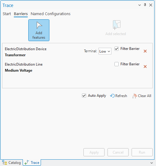
Features are added to the Trace pane and are ready to be used in a trace. On the Barriers tab, the Filter Barrier check box is displayed for each barrier. Check this box if you want the barrier to serve as a filter barrier. To learn more, see Feature barriers.
See the Work with features in the Trace pane section below to learn more about interacting with trace locations.
Add selected features or objects from the map view or attribute table
You can set selected network features on a map or attribute table as starting points, stopping points, or barriers. Complete the steps below to set trace locations using network features that are selected on the map or to add selected nonspatial junction or edge objects to serve as trace locations. This workflow uses the Start, Stop, and Barriers tabs in the Trace pane, with Auto Apply unchecked.
Select one or more network features on the map or attribute table to use as starting points or barriers.
On the Utility Network tab, in the Tools group, click Trace to open the Trace pane.
Tip:
Use the Trace drop-down arrow
 to set the active tab in the pane to be Start , Stop , or Barriers .
In the Trace pane, confirm that the Start, Stop, or Barriers tab is active.
In the Trace pane, ensure that the Auto Apply check box is unchecked.
In the Trace pane, on the Start, Stop, or Barriers tab, click Add selected.
The selected network features are added to the Start, Stop, or Barriers tabs in the Trace pane with an asterisk, indicating that they are not committed.
When trace locations are added from selected spatial features on the map or attribute table, the following occurs:
A gray circle appears where you clicked to represent a starting point.
A red octagon appears where you clicked to represent a stopping point.
A gray X appears where you clicked to represent a barrier.
When trace locations are added from selected records in the edge or junction object attribute table, the feature or features added to the Start, Stop, or Barriers tabs in the Trace pane are not represented by a symbol in the map view.
If you pass in a device or junction object with terminals, use the Terminal drop-down list to set the correct terminal as the starting point, stopping point, or barrier.
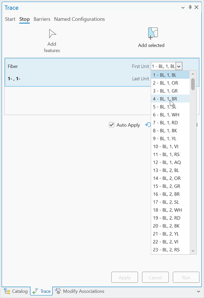
When a trace location is defined on a grouped object in a telecom domain network with unit identifiers (or unit IDs, units), all units available to be traced are loaded to the Trace pane. You can change the First Unit and Last Unit values to constrain the units to which the location applies. When a color scheme has been applied to the edge object, this is displayed in a drop-down list when selecting the First Unit value.
Click Apply.
The gray icons on the map turn green for starting points and red for stopping points and barriers, indicating that they are ready to be used by a trace. A temporary feature class is created in the project's home geodatabase: UN_Temp_Starting_Points for starting points, UN_Temp_Stopping_Points for stopping points, and UN_Temp_Barriers for barriers.
Features are added to the Start, Stop, or Barriers tabs in the Trace pane and are ready to be used in a trace.
Work with features in the Trace pane
When features are added as trace locations, they are added to the Trace pane. You can interact with these features directly to perform the following tasks:
To place additional trace locations, use Add features to select network features in the map or use Add selected to load selected features to the map or attribute table.
To remove existing trace locations, click the delete button
 next to each feature, or click Clear All
  to remove all features set on the Start, Stop, or Barriers tabs. The Trace command reveals a Clear All command that can be used to clear all features set as trace locations. This also unselects the active named trace configuration on the Named Configuration tab.
On the Barriers tab, an optional Filter Barrier check box is displayed for each barrier. Check this box if you want the barrier to serve as a filter barrier. To learn more, see Feature barriers.
To interact with features in the map view, right-click and choose from the following options:
Flash

Zoom To

Pan To

Pop-up

Select

Unselect

To interact with nonspatial features in the pane, right-click and choose from the following options:
Pop-up
Select
Unselect
Tracing options
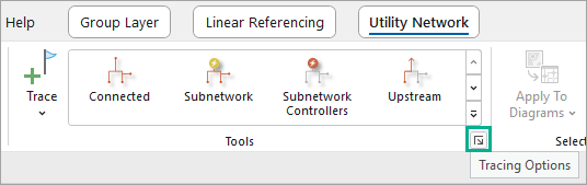
Tracing options allow you to control how trace locations are added to the Trace pane. You can configure these options on the Tracing tab of the Network Options dialog box. To access these options, click the Tracing Options dialog box launcher ![]() on the Utility Network tab at the lower right of the Tools group. The Network Options dialog box appears with the Tracing tab active.
on the Utility Network tab at the lower right of the Tools group. The Network Options dialog box appears with the Tracing tab active.
The Maximum number of starting points and barriers to add at once parameter specifies the number of trace locations that can be created at the same time without a prompt. The default setting is 10. If more locations are selected on the map or added from a selection to the Trace pane, a dialog box appears, prompting you to confirm that you want to proceed with the selected number of trace locations.