Manage Pipeline Referencing and a utility network together
![]() Available with Location Referencing license.
Available with Location Referencing license.
A linear referencing system (LRS) can be used with a gas utility network in ArcGIS by integrating the ArcGIS Pipeline Referencing centerline feature class and the ArcGIS Utility Network Pipeline Line feature class.
A utility network is a comprehensive framework for modeling utility systems, such as gas and electric. The utility network models all the components that make up the system, such as pipes, valves, and devices, allowing you to simulate real-world behavior in the features that you model.
The sections below describe the data model changes needed to take advantage of both an LRS and a utility network. This includes guidance on loading data and publishing services with data managed by both products. Additionally, there are changes to editing and analysis tools that use data referenced by Pipeline Referencing and Utility Network.
Note:
To work with both Pipeline Referencing and Utility Network data, you can download the Unified Pipeline Tools add-in and install it in ArcGIS Pro. The add-in is also included in the 2.3 and later releases of the Gas and Pipeline Referencing Utility Network Foundation solution, which features the Utility and Pipeline Data Model (UPDM) and includes common gas and pipeline data management workflows. The following is information about the add-in:
You can further manage it in ArcGIS Pro.
The add-in contains the commonly used tools from the Location Referencing, Utility Network, Map, Selection, and Editing ribbon tabs to streamline workflows in a combined Pipeline Referencing and Utility Network environment.
The Gas and Pipeline Referencing Utility Network Foundation solution is not required to use the add-in. After the add-in is installed, it is displayed as a tab on the ArcGIS Pro ribbon. The availability of tools in the add-in is determined by the associated data and licenses.
Requirements
You can use an out-of-the-box data model or customize a data model to meet your organization's rules and requirements, as long as the required feature classes and tables in the Pipeline Referencing data model and the UPDM are present. The UPDM contains all of the feature classes, tables, and relationship classes needed to support both a utility network and an LRS in a single geodatabase.
You can simplify the deployment process for a utility network based on the UPDM using the following tools:
Learn more about utility network creation and configuration
To create a custom data model other than the UPDM, ensure that the required feature classes and tables for a utility network and an LRS are present. This includes the shared centerline feature class, which must be part of both the utility network and the LRS.
In the Gas and Pipeline Referencing Utility Network Foundation solution, the Pipeline Line feature class represents all of the pipes in the system. In a combined Utility Network and Pipeline Referencing deployment, the Pipeline Line feature class also serves as the LRS centerline feature class.
Additionally, the gas configuration of a utility network contains many critical attributes modeled on the Pipeline Line feature class. This shared feature class described below is the integration point between the two products. In the past, these attributes would have been modeled as separate LRS events. To prevent the need to model these attributes in different feature classes, the Pipeline Line feature class can also have route and measure fields modeled, such as an event that can be updated using the Pipeline Referencing tools.
Note:
In the Pipeline Line feature class, you must specify the double data type for the From Measure and To Measure fields, and their precision and scale values should match those of the calibration point feature class.
Additional utility network feature classes such as Pipeline Device and Pipeline Junction can also store routes and measures. To store routes and measures in these feature classes, add route ID and measure fields to them. The route and measure attributes can be calculated using the Update Measures From LRS tool. None of the utility network feature classes should be registered as LRS events.
Note:
Use the Configure Utility Network Feature Classes tool to configure the Pipeline Line, Pipeline Device, and Pipeline Junction feature classes for use with an LRS.
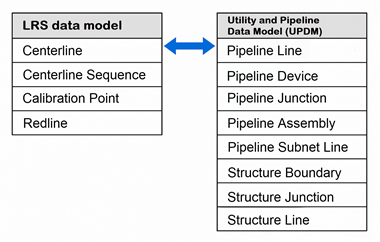
The following are required feature classes for the Pipeline Referencing schema to integrate with Utility Network:
Centerline
Centerline Sequence
Calibration Point
Redline
The following are required gas data model feature classes for the Utility Network schema to integrate with Pipeline Referencing:
Pipeline Line
Pipeline Device
Pipeline Junction
Pipeline Assembly
Pipeline Subnet Line
Structure Boundary
Structure Junction
Structure Line
The following fields must be present in the Pipeline Line feature class to successfully configure it for use with an LRS and to take advantage of all Pipeline Referencing and Utility Network capabilities:
| Field | Data type | Length | IsNullable | Description |
|---|---|---|---|---|
| Centerline ID | GUID | N/A | Yes | The unique ID for centerline geometry. |
| Route ID | String or GUID | Same type and length as route ID in the centerline sequence table. | No | The unique ID for each route in the network. |
| From Measure | Double | N/A | Yes | The measure on the route where the beginning of the feature is located. |
| To Measure | Double | N/A | Yes | The measure on the route where the end of the feature is located. |
The following fields must be present in the Pipeline Device and Pipeline Junction feature classes to successfully configure them for use with an LRS and to take advantage of all Pipeline Referencing and Utility Network capabilities:
| Field | Data type | Length | IsNullable | Description |
|---|---|---|---|---|
| Route ID | String or GUID | Same type and length as route ID in the centerline sequence table. | No | The unique ID for each route in the network. |
| Measure | Double | N/A | Yes | The measure on the route where the feature is located. |
Model linear-referenced and non-linear-referenced pipe characteristics in a single event feature class
In a combined LRS and Utility Network deployment, both linear-referenced and non-linear-referenced pipe characteristics can be modeled in a single event feature class. You can query and analyze pipe characteristics without creating additional data views or temporary layers.
The Generate Events tool’s Bypass events with null route ID and measure fields parameter allows you to bypass non-linear-referenced event features that have null route ID and measure fields. By doing so, the shapes and attributes of non-linear-referenced event features remain unchanged.
Configure, load data, and publish a utility network and an LRS
Both Pipeline Referencing and Utility Network have specific requirements and steps to correctly deploy in a geodatabase. While a utility network can be manually configured, explore the Utility Network Package toolbox to simplify the configuration of a utility network.
To deploy an LRS and a utility network in a geodatabase, complete the following steps:
Apply an asset package (such as the gas configuration).
Create an LRS using one of the following tools:
Create LRS—Create an LRS and minimum schema items from scratch.
Create LRS From Existing Dataset—Create an LRS from existing feature classes that are not yet registered with an LRS.
Learn more about creating an LRS
Note:
Ensure that the correct spatial reference; x,y,z and m-tolerance; and x,y,z and m-resolution are configured for feature classes used by Pipeline Referencing and Utility Network so that the LRS can be configured correctly.
Learn more about tolerance and resolution settings in the LRS
If you ran the Create LRS tool, complete the following steps to configure the LRS and utility network together:
Change the centerline feature class registered with the LRS from the original centerline feature class to the Pipeline Line feature class using the Modify LRS tool.
Configure the Pipeline Line, Pipeline Device, and Pipeline Junction feature classes for use with an LRS using the Configure Utility Network Feature Classes tool.
If you ran the Create LRS From Existing Dataset tool, configure the Pipeline Line, Pipeline Device, and Pipeline Junction feature classes for use with an LRS using the Configure Utility Network Feature Classes tool.
Create LRS Networks using one of the following tools:
Create LRS events using one of the following tools:
Learn more about creating LRS events
Note:
Utility network feature classes such as Pipeline Line, Pipeline Device, and Pipeline Junction should not be registered as LRS events. The route and measure fields on these feature classes can be updated using the Update Measures From LRS tool.
Load data into the utility network using the Append tool and into the LRS using the Append Routes and Append Events tools.
Note:
The Append tool loads features into the Pipeline Line feature class. Use this tool first to load the feature class with features that have the following:
Centerline ID populated
Utility network and user-managed fields populated
The Append Routes tool considers existing centerlines when appending routes. When a centerline ID already exists where you append a route, the existing centerline sequence record is updated with the route ID of the appended route.
Prepare data and publish a utility network and an LRS as a feature service.
Note:
To use the capabilities of both products, a feature service with layers from both a utility network and an LRS must be published.
Combined LRS and utility network data editing
When using ArcGIS Pro to edit a feature service with both LRS and utility network data, some LRS editing workflows differ.
Route editing
When the Pipeline Line feature class serves as the LRS centerline feature class, the following additional requirements apply to route creation and editing steps:
The
Route IDfield from the Pipeline Line feature class must be associated with the LRS to ensure that pipes and centerlines added to the Pipeline Line feature class remain traceable and verifiable to their source documents. Optionally, theFrom MeasureandTo Measurefields can be populated in the centerline feature class.Note:
If the measures are not provided using the centerline feature class, the LRS route editing tools provide start and end measures on the route.
When centerlines are used in the Create, Extend, or Realign Route tools, the attribute values in the
Route ID,From Measure, andTo Measurefields are updated as part of the edit activity. Calibration points are placed at the beginning and end of each centerline segment in the edit activity, which ensures that measures on the route in the LRS Network do not change when other edits take place along the route over time. This ensures that the Pipeline Line feature class remains traceable and verifiable to the source document used to input the pipe.When the centerlines are edited using the Retire, Reassign, or Realign Route tools, the centerlines are split and the attribute values in the
Route ID,From Measure, andTo Measurefields of the split pipelines are updated. Calibration points are placed at the beginning and end of each centerline segment in the edit activity, which ensures that measures on the route in the LRS Network do not change when other edits take place along the route over time. This ensures that the Pipeline Line feature class remains traceable and verifiable to the source document used to input the pipe.When you split a centerline associated to a route using any of the Pipeline Referencing centerline feature class editing tools, the
Route ID,From Measure, andTo Measureattribute values of the split pipelines are updated and a calibration point is added at the split location.
Centerline and route creation
The table and diagram below show centerline attributes before route creation.
Note:
The centerline feature class's start and end measures are used during route creation and editing using the Create, Extend, or Realign Route editing tools. If the measures are not provided in the centerline feature class, the LRS route editing tools provide the start and end measures.
In the following route creation examples, the start measure (
From Measure) and end measure (To Measure) values are prepopulated on the centerlines.
Centerline attributes before route creation
|
OID |
Route ID |
From Measure |
To Measure |
|---|---|---|---|
|
1201 |
<null> |
0 |
104.35 |
|
1202 |
<null> |
104.35 |
177.89 |
|
1203 |
<null> |
177.89 |
265.27 |

The following table and diagram show centerline attributes after route creation:
Centerline attributes after route creation
|
OID |
Route ID |
From Measure |
To Measure |
|---|---|---|---|
|
1201 |
{7a765e36-dbb0-43f9-a1f1-b6f37a4e445a} |
0 |
104.35 |
|
1202 |
{7a765e36-dbb0-43f9-a1f1-b6f37a4e445a} |
104.35 |
177.89 |
|
1203 |
{7a765e36-dbb0-43f9-a1f1-b6f37a4e445a} |
177.89 |
265.27 |

Route attributes
|
OID |
Route ID |
Route Name |
|---|---|---|
|
1000 |
{7a765e36-dbb0-43f9-a1f1-b6f37a4e445a} |
Route 17A-South |
A centerline split by point
The following table and diagram show a centerline that is associated with a route and its attributes before being split using the Split Centerline By Point tool:
|
OID |
Route ID |
From Measure |
To Measure |
|---|---|---|---|
|
1201 |
{7a765e36-dbb0-43f9-a1f1-b6f37a4e445a} |
0 |
104.36 |

The start and end measure values of the associated route are updated after the centerline is split.
The following table and diagram show the centerline and its attributes after the split operation:
|
OID |
Route ID |
From Measure |
To Measure |
|---|---|---|---|
|
1201 |
{7a765e36-dbb0-43f9-a1f1-b6f37a4e445a} |
0 |
52.18 |
|
1202 |
{7a765e36-dbb0-43f9-a1f1-b6f37a4e445a} |
52.18 |
104.36 |

Centerlines split by an LRS edit
In the following scenario, a centerline is split and its From Measure, To Measure, and Route ID attribute values are updated after a portion of the route is retired.
The following table and diagram show the centerline and the route attributes before the edit activity:
|
OID |
Route ID |
From Measure |
To Measure |
|---|---|---|---|
|
1201 |
{7a765e36-dbb0-43f9-a1f1-b6f37a4e445a} |
0 |
104.36 |
The route is retired from the start of the route to the middle portion of the route. As a result, the centerline is split, and its measures are updated.
The following table and diagram show the centerline and its attributes after the retire route edit activity:
|
OID |
Route ID |
From Measure |
To Measure |
|---|---|---|---|
|
1201 |
{7a765e36-dbb0-43f9-a1f1-b6f37a4e445a} |
0 |
52.18 |
|
1202 |
{7a765e36-dbb0-43f9-a1f1-b6f37a4e445a} |
52.18 |
104.36 |

Edit a service with LRS and utility network data in ArcGIS Pro
To edit a feature service that contains LRS and utility network data, complete the following steps:
Create and update any pipelines or centerlines intended for use in LRS editing activities:
Note:
If measure values are provided in the centerline feature class before route editing, they appear as suggested measures while creating or editing routes using the Create, Extend, or Realign Route tools. If measures are not provided, the LRS route editing tools suggest measures.
Optionally, provide a start measure value and an end measure value for the centerlines.
Optionally, validate the network topology to ensure that newly created or updated pipes are valid.
Complete the LRS editing activity.
Note:
In the create, extend, and realign route workflows, more calibration points are created at centerline endpoints along the route, and the
Route IDfield for the centerlines used in these tools is now populated with the route with which the centerline is associated.Run the Apply Event Behaviors tool and any other tools necessary to update the derived network and events.
If other utility network feature classes have route and measure fields modeled, update them using the Update Measures From LRS tool.
Validate the network topology to ensure all edits are valid.
To add or edit LRS events, use the Location Referencing tab event editing tools in ArcGIS Pro or the Location Referencing widgets in ArcGIS Experience Builder.
Analysis capabilities in a combined LRS and utility network
Another advantage of configuring an LRS and a utility network in a single geodatabase is the combined analysis capabilities of both products on a pipeline system. You can check for connectivity and traversability on the entire utility network, its subnetworks, or upstream and downstream of specific network areas.
The LRS is typically used by various integrity and compliance applications for analysis and reporting. Many of these processes apply dynamic segmentation using the Overlay Events tool. When the Pipeline Line, Pipeline Device, and Pipeline Junction feature classes in a utility network are configured for use with an LRS using the Configure Utility Network Feature Classes tool, these feature classes can be included with networks and events in the Overlay Events tool for dynamic segmentation, allowing these features and their attributes to be included without modeling separate events.